Push bending forming device adopting push-pull integrated loading and method

An integrated, supporting device technology, applied in the field of pipe bending and forming, can solve the problems of difficulty in precise angle positioning, large footprint, and difficult adjustment, and achieve the effect of reducing manufacturing costs, reducing production time, and not easy to wrinkle

Active Publication Date: 2018-12-28
NANCHANG HANGKONG UNIVERSITY
View PDF5 Cites 2 Cited by
  • Summary
  • Abstract
  • Description
  • Claims
  • Application Information

AI Technical Summary

Problems solved by technology

When pushing and bending pipe fittings with different bending angles, a special swing angle mechanism is often required to adjust the angle between the push cylinder and the jack cylinder, which is difficult to adjust, difficult to accurately position the angle, high equipment cost, and a large footprint

Method used


Image

  • Push bending forming device adopting push-pull integrated loading and method
  • Push bending forming device adopting push-pull integrated loading and method
  • Push bending forming device adopting push-pull integrated loading and method

Examples


Embodiment 1

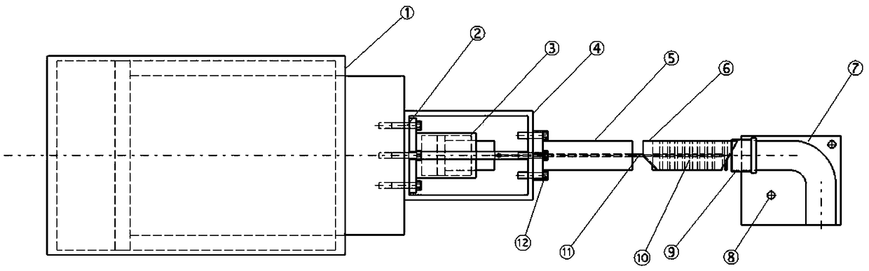
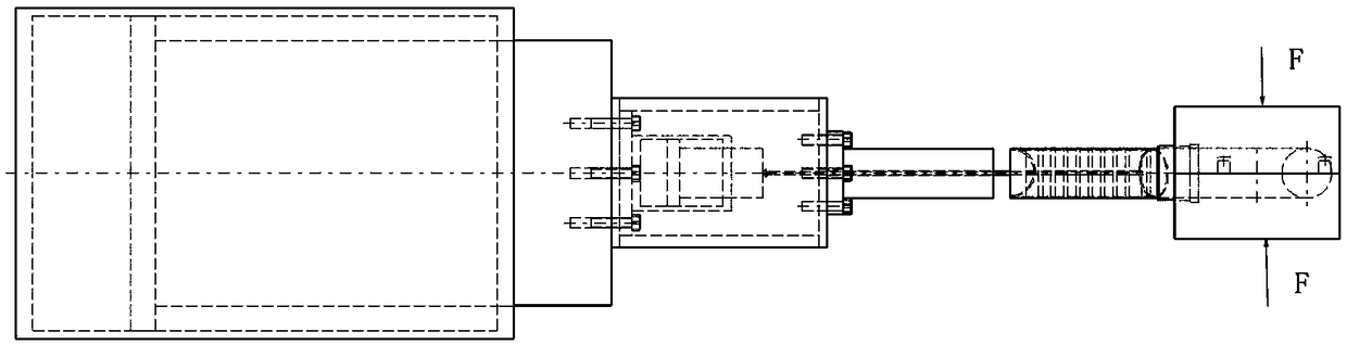
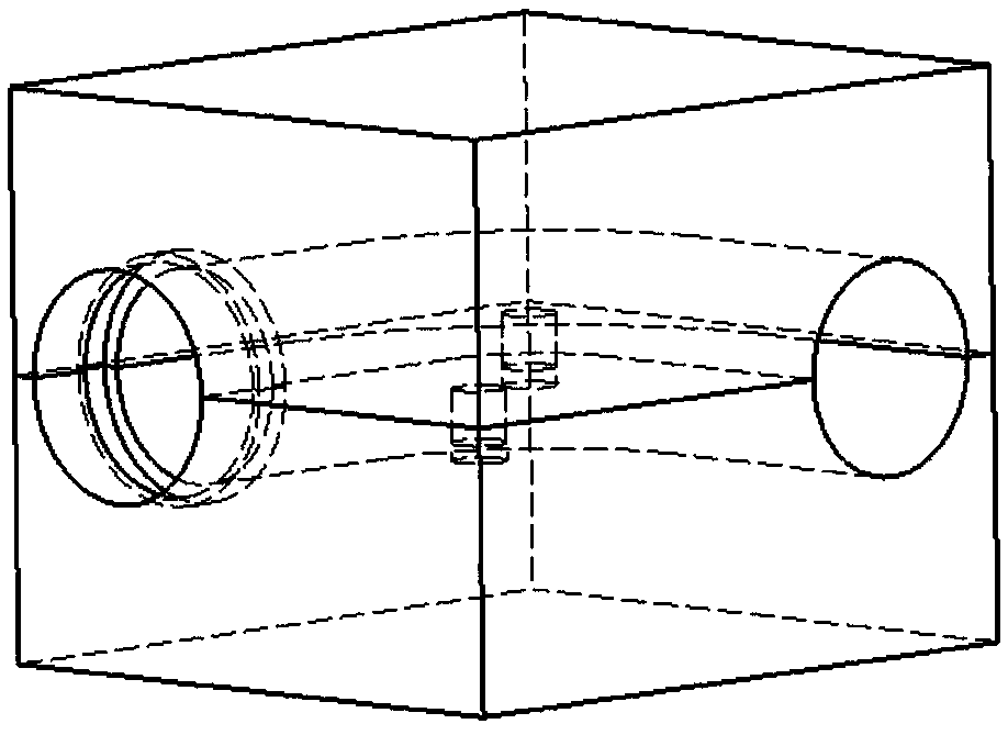
[0040] Such as Figure 1-5 As shown, the present embodiment provides a push bending forming device that adopts push-pull integrated loading, including a main push cylinder 1, a support device, a push rod 5, a blank tube 6 and a mold 7, the support device is installed on the output end of the main push cylinder 1, and the push One end of the rod 5 is installed on the front end of the support device, specifically, the support device includes a support box 4, the rear end surface of the support box 4 is fixed on the output end of the main push cylinder 1 by the first locking bolt 2, and the tail of the push rod 5 The end is fixed on the front end surface of the supporting box 4 by the second locking bolt 12 . The mold 7 is located in front of the blank tube 6, and the other end of the push rod 5 is used to push the blank tube 6 to move towards the mold 7, and the end of the mold 7 close to the blank tube 6 is provided with a guide sleeve 9 to precisely guide the blank tube 6 , t...


PUM


Abstract

The invention discloses a push bending forming device adopting push-pull integrated loading and a method. The push bending forming device comprises a main push cylinder, a supporting device, a push rod, a blank pipe and a die, wherein the supporting device is installed at the output end of the main push cylinder, one end of the push rod is installed at the front end of the supporting device, and the other end of the push rod pushes the blank pipe to move towards the die; the die is positioned in front of the blank pipe, and the blank pipe is sequentially filled with a plurality of polyurethanefilling blocks; an auxiliary hydraulic cylinder is arranged in the supporting device, the tail part of the auxiliary hydraulic cylinder is fixed to the inner wall of the rear end surface of the supporting device, and the output end is arranged towards the push rod; and a steel wire rope is detachably connected to the output end of the auxiliary hydraulic cylinder, the other end of the steel wirerope penetrates through the push rod, and the polyurethane filling blocks are sequentially connected to the other end of the steel wire rope. According to the push bending forming device adopting push-pull integrated loading and the method, the push cylinder and a top cylinder are integrated, the angles of the push cylinder and the top cylinder do not need to be adjusted when pipes are bent with different angles, and the supporting mode of the polyurethane filling blocks is changed meanwhile, so that efficient push bending forming of the pipes is realized.

Description

technical field [0001] The invention relates to the technical field of pipe bending, in particular to a push-bending device and method that adopt push-pull integrated loading. Background technique [0002] The push bending forming process is a process applied to the bending and forming of small bending radius pipes, and is often used in the forming of aerospace small bending radius pipes. At present, the push bending process usually pushes the tube blank into the mold cavity by the push head. There is a polyurethane filler block inside the tube blank. One end of the polyurethane filler block is attached to the push head, and the other end is supported by the ejector rod to ensure that the tube blank There is a certain internal pressure inside to avoid wrinkling of the tube blank during push bending. Therefore, during push bending, in addition to the clamping force of the mold, it is also necessary to have push cylinders and jack cylinders distributed at both ends of the ben...

Claims


Application Information

Patent Timeline
IPC IPC(8): B21D9/03B21D9/12
CPCB21D9/03B21D9/125
Inventor 徐雪峰吴孔炜吴义旺肖洁付春林
Owner NANCHANG HANGKONG UNIVERSITY
Why Eureka
Try Eureka