Check patentability & draft patents in minutes with Patsnap Eureka AI!

Vertical shaft type cantilever robot

A robot, vertical axis technology, applied in the field of truss robots, can solve the problems of inconvenient transfer, high labor cost, low production efficiency, etc.

Pending Publication Date: 2018-12-28
KOCEL INTELLIGENT FOUNDRY IND INNOVATION CENT CO LTD
View PDF12 Cites 6 Cited by
  • Summary
  • Abstract
  • Description
  • Claims
  • Application Information

AI Technical Summary

Problems solved by technology

[0003] Aiming at the deficiencies of the prior art, the present invention provides a vertical-axis cantilever robot. A technical problem solved by one aspect disclosed by the present invention is the inconvenient transfer of items within the non-working radius in the prior art and the efficiency of secondary transfer. The problem of low cost, using the vertical axis cantilever robot, solves the problems of high labor cost and low production efficiency in the production line of loading and unloading, workpiece turning, and workpiece reordering

Method used


Image

  • Vertical shaft type cantilever robot
  • Vertical shaft type cantilever robot
  • Vertical shaft type cantilever robot

Examples


Embodiment 1

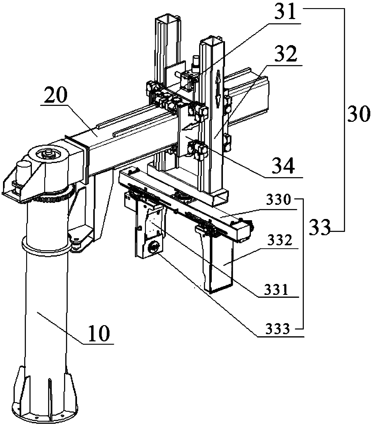
[0023] A vertical axis type cantilever robot, comprising a column 10, a rotating beam 20, and a manipulator 30; the manipulator 30 is installed on the rotating beam 20, and one end of the rotating beam 20 is axially connected to the column 10; the rotating beam 20 includes an extension arm 21 and a shaft part 22 , the support part 23, the rotating shaft part 22 is arranged on the extension arm 21, and is connected with the column 10 axis, and the extension arm 21 is slidably connected with the manipulator 30, and one end of the support part 23 is connected with the extension arm 21, and the other end is connected with the column 10 Swipe to connect.

[0024] Using the column 10 and the rotating beam 20 improves the gripping ability of the manipulator 30, so that within a certain range, the manipulator 30 can complete the work of grabbing or carrying heavy objects.

Embodiment 2

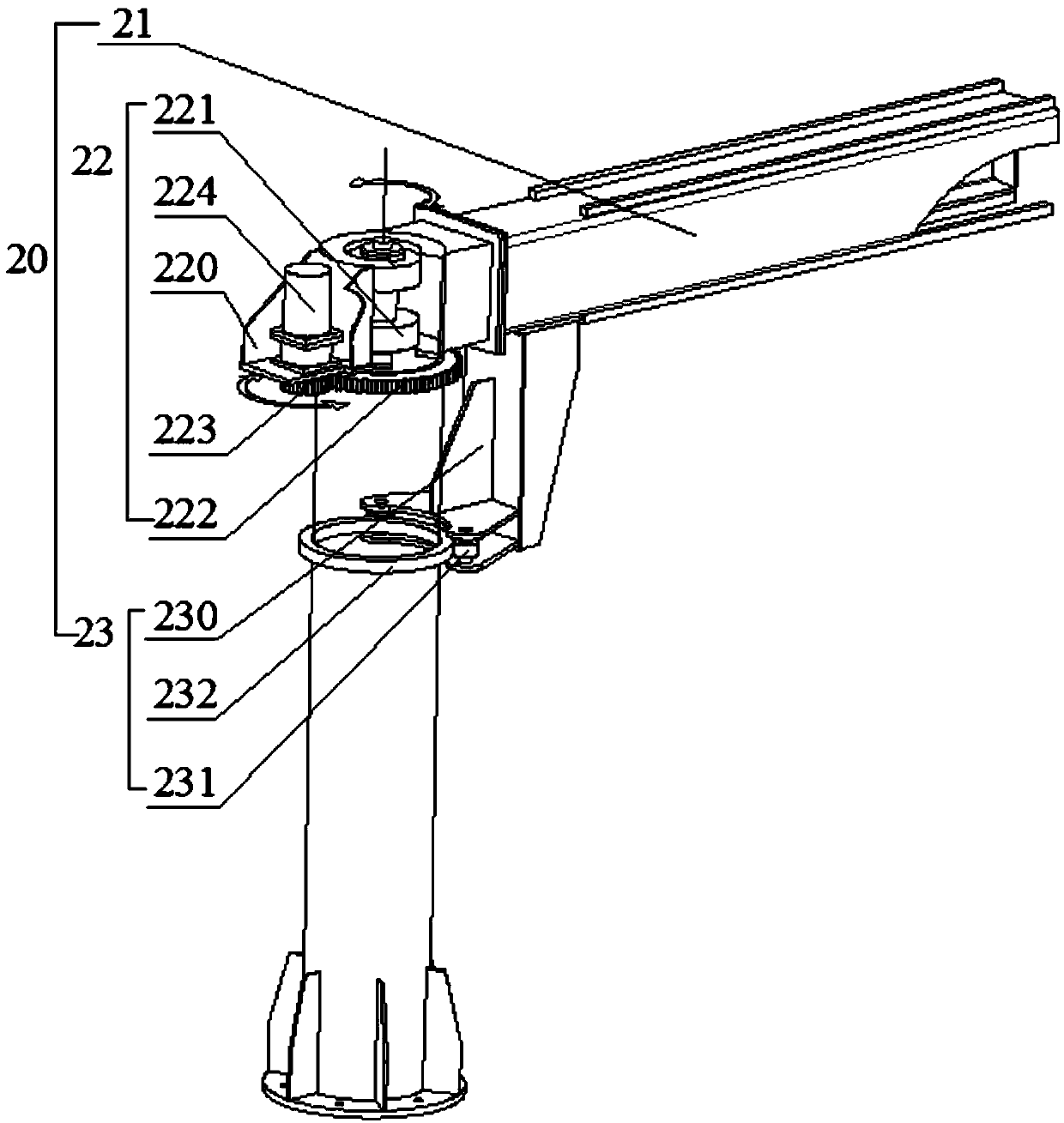
[0026] A vertical axis type cantilever robot, comprising a column 10, a rotating beam 20, and a manipulator 30; the manipulator 30 is installed on the rotating beam 20, and one end of the rotating beam 20 is axially connected to the column 10; the rotating beam 20 includes an extension arm 21 and a shaft part 22 , the support part 23, the rotating shaft part 22 is arranged on the extension arm 21, and is connected with the column 10 axis, the extension arm 21 is slidably connected with the manipulator 30, the support part 23 includes a fixed arm 230, a pulley 231, a slide rail 232, fixed One end of the arm 230 is fixedly connected with the extension arm 21 , and the other end is provided with a pulley 231 , and the column 10 is provided with a slide rail 232 , and the pulley 231 slides along the slide rail 232 .

[0027] The support part 23 is provided with at least two pulleys 231, and the slide rail 232 forms a circle around the column 10. The side of the fixed arm 230 where ...

Embodiment 3

[0030] Refer to attached figure 2 Shown, a kind of vertical axis type cantilever robot comprises column 10, rotating beam 20, manipulator 30; Manipulator 30 is installed on the rotating beam 20, and one end of rotating beam 20 is connected with column 10 axis; Rotating beam 20 comprises extending arm 21, The rotating shaft part 22, the support part 23, the rotating shaft part 22 is arranged on the extension arm 21, and is connected with the column 10 axis, on the extension arm 21, a manipulator 30 is slidably connected, and the support part 23 includes a fixed arm 230, a pulley 231, a slide rail 232 , one end of the fixed arm 230 is fixedly connected with the extension arm 21 , and the other end is provided with a pulley 231 , the column 10 is provided with a slide rail 232 , and the pulley 231 slides along the slide rail 232 .

[0031] The rotating shaft part 22 includes a housing 220, a bearing 221, a fixed gear 222, a rotating gear 223, and a driving device 224. The bearin...


PUM


Abstract

Disclosed is a vertical shaft type cantilever robot. The vertical shaft type cantilever robot comprises a stand column, a rotary beam and a mechanical arm, wherein the mechanical arm is mounted on therotary beam, and one end of the rotary beam is in shaft connection with the stand column; the rotary beam comprises an extending arm, a rotating shaft unit and a support unit, the rotating shaft unitis arranged on the extending arm and in shaft connection with the stand column; the extending arm is slidingly connected with the mechanical arm, one end of the support unit is connected with the extending arm, and the other end of the support unit is slidingly connected with the stand column. With the stand column as the support member of the truss mechanical arm, the vertical shaft type cantilever robot can complete carrying or rotating operation within the circular motion range of the rotary beam and is qualified to carrying weights, thereby solving the problems of high cost and low production efficiency of feeding, discharging, workpiece rotation and workpiece transfer on a production line.

Description

technical field [0001] The invention relates to the field of truss robots, in particular to a vertical axis type cantilever robot. Background technique [0002] In process production, in order to place the items to be grabbed or transferred within the effective working range of the transfer or grabbing equipment, one method is that the operator places the items to be transferred within the effective working range of the transfer equipment through a third-party tool or means. Within the scope, this kind of secondary transfer has caused the low logistics efficiency of the goods in the production process, which seriously affects the efficiency of the production line; another way is to use joint robots to grab workpieces, but due to structural limitations, they can only grab workpieces of about 500kg. And the cost of joint robot is relatively high. Contents of the invention [0003] Aiming at the deficiencies of the prior art, the present invention provides a vertical-axis ca...

Claims


Application Information

Patent Timeline
IPC IPC(8): B25J9/04
CPCB25J9/04
Inventor 杨光明闫涛冯艳艳赵以麟黄部东马睿
Owner KOCEL INTELLIGENT FOUNDRY IND INNOVATION CENT CO LTD
Features
  • R&D
  • Intellectual Property
  • Life Sciences
  • Materials
  • Tech Scout
  • Unparalleled Data Quality
  • Higher Quality Content
  • 60% Fewer Hallucinations
Learn More