
cutting device

A technology for cutting devices and workpieces, which is applied in the direction of instruments, televisions, work accessories, etc., can solve the problem of inaccurate measurement of cutting groove width, etc., and achieve the effects of shortening time, efficient shooting, and accurate measurement

Active Publication Date: 2021-12-21
DISCO CORP
View PDF7 Cites 0 Cited by
  • Summary
  • Abstract
  • Description
  • Claims
  • Application Information

AI Technical Summary

Problems solved by technology

[0008] However, there is a problem that, since the ejection of air has directionality, when there are droplets of cutting water around the direction in which the air is ejected, the droplets are drawn into the ejection direction of the air, although they are directed toward the workpiece. Air is ejected, but fine water droplets also adhere to the upper surface of the workpiece
In the past, the cutting process was temporarily stopped, and the cutting position and the width of the cutting groove (debris on both sides of the cutting groove) were inspected by taking pictures with a video camera. However, when fine water droplets adhered to the upper surface of the workpiece, it was impossible to To accurately measure the groove width of the cutting groove, it is necessary to dry the upper surface of the workpiece

Method used


Image

  • cutting device
  • cutting device
  • cutting device

Examples


Embodiment Construction

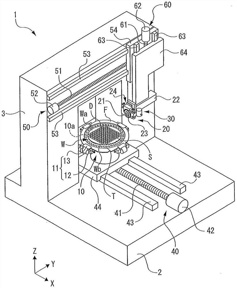
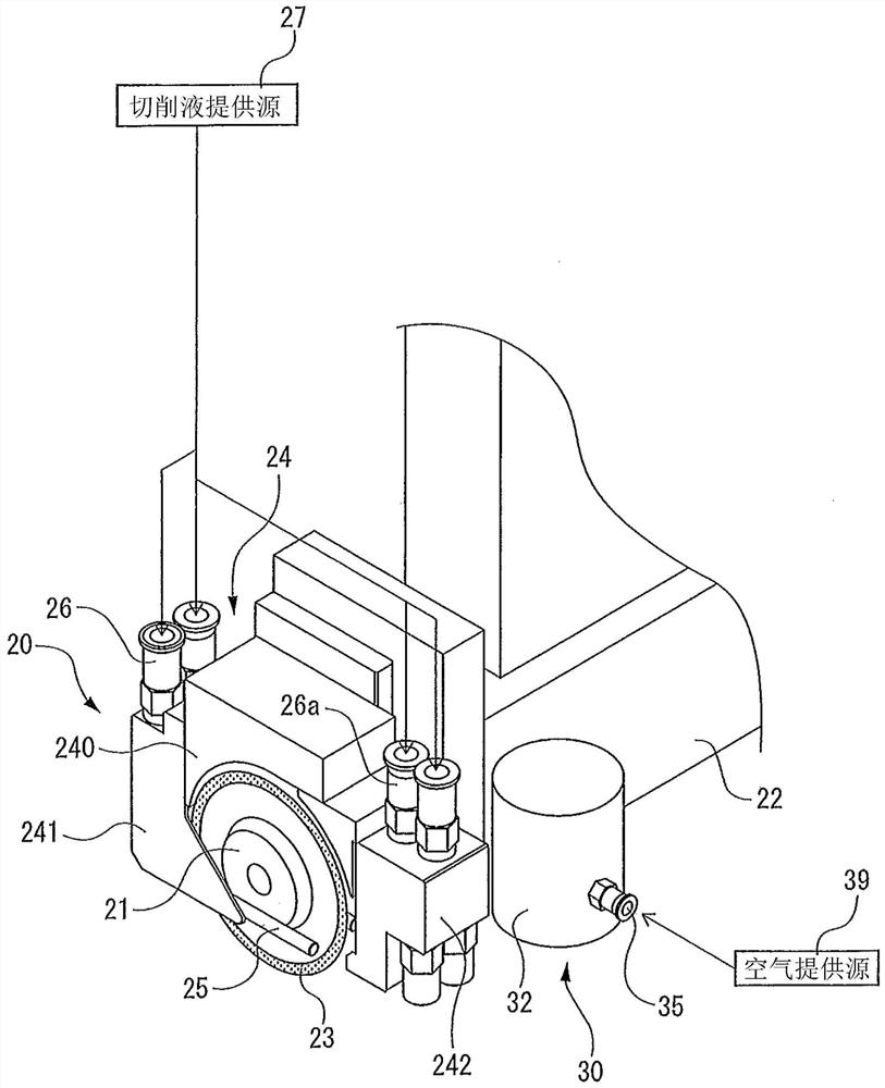
[0024] figure 1 The cutting device 1 shown has a device base 2, and includes: a holding table 10 disposed on the device base 2 for holding a plate-shaped workpiece W as a workpiece; a cutting unit 20 for holding The cutting tool 23 is rotatably mounted, and performs cutting while supplying cutting water to the plate-shaped workpiece W held by the holding table 10; the imaging unit 30 photographs the plate-shaped workpiece W held by the holding table 10 from above. ; the moving unit 40, which makes the holding table 10 and the imaging unit 30 relatively move in the cutting feed direction (X-axis direction); The cutting unit 20 performs index feeding; and the raising and lowering unit 60 raises and lowers the cutting unit 20 in the vertical direction (Z-axis direction).

[0025] The upper surface of the holding table 10 serves as a holding surface 10a for holding the plate-shaped workpiece W. As shown in FIG. A plurality of frame holding units 11 for holding an annular frame F...


PUM


Abstract

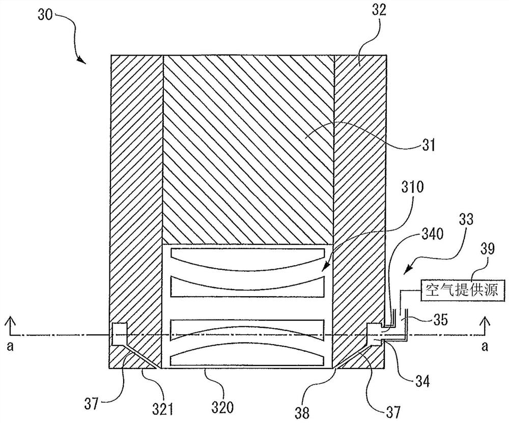
To provide a cutting device capable of efficiently photographing cutting grooves formed in a workpiece. The cutting device (1) has an imaging unit (30) for photographing the plate-shaped workpiece (W) held by the holding table (10). ) between the bottom (321) of the plate-shaped workpiece and the air layer forming unit (33) of the air layer, the air layer forming unit (33) has: an annular air path (34), which takes the optical axis of the objective lens (310) as the center; air inlet (35), which introduces air to the annular air path (34); guide plate (36), which makes the air swirl in one direction in the annular air path (34) to generate a vortex flow; and The reverse annular conical flow path (37), its diameter shrinks downward from the annular air path (34), when shooting the cutting groove (G), a vortex air flow (101 ) of the high-pressure air layer (100), the cutting water remaining on the upper surface (Wa) of the plate-shaped workpiece and the cutting groove is blown away by the vortex air flow (101), so that the groove width of the cutting groove can be measured more accurately.

Description

technical field [0001] The present invention relates to a cutting device for cutting a workpiece. Background technique [0002] A cutting device that cuts a workpiece includes at least: a holding table that holds the workpiece; a cutting unit that cuts the workpiece held on the holding table; and an imaging camera (microscope) that photographs the workpiece. The processed surface of the object. The imaging camera is housed in the case to prevent the cutting water and machining chips used in the cutting process from adhering. An opening for shooting is formed at the bottom of the casing, and an openable and closable shutter is attached to the opening. When photographing a workpiece, the shutter is opened to open the aperture. Then, when the workpiece is not photographed, the opening is closed by shielding the opening with a shutter, thereby preventing droplets (water droplets) of cutting water used in the cutting process from adhering to the objective lens of the imaging c...

Claims


Application Information

Patent Timeline
Patent Type & Authority Patents(China)
IPC IPC(8): B28D1/24B28D7/00B28D7/04B28D7/02H04N5/225
CPCB28D1/24B28D7/00B28D7/02B28D7/04H04N23/50H04N23/57H04N23/55H04N23/51H04N23/54H01L21/67092H01L21/67028G02B21/36
Inventor 丹野宁
Owner DISCO CORP
Learn More