Reinforcement binding alignment device

A steel bar, symmetrical technology, applied in the field of automatic steel bar processing, can solve the problem of identifying the number and type errors, and achieve the effect of facilitating the collection of accurate images, improving technical effects, and improving accuracy.

Inactive Publication Date: 2018-12-28
四川知创知识产权运营有限公司
View PDF0 Cites 11 Cited by
  • Summary
  • Abstract
  • Description
  • Claims
  • Application Information

AI Technical Summary

Problems solved by technology

[0004] The invention provides a steel bar binding and alignment device, which solves the technical problem that the existing steel bar recognition system recognizes the wrong number and type, realizes the end face alignment and binding processing of the steel bars, facilitates the collection of accurate images, and improves the steel bar recognition system. The technical effect of the accuracy rate

Method used


Image

  • Reinforcement binding alignment device
  • Reinforcement binding alignment device
  • Reinforcement binding alignment device

Examples


Embodiment Construction

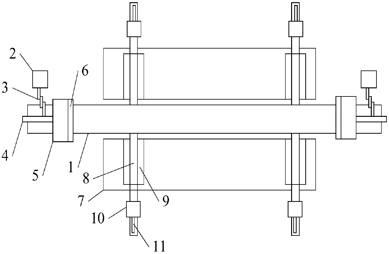
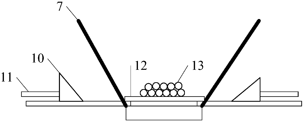
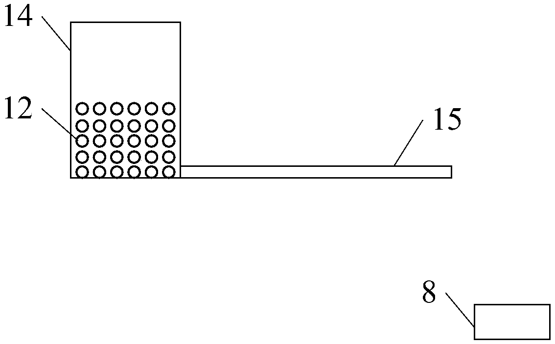
[0022] The invention provides a steel bar binding and alignment device, which solves the technical problem that the existing steel bar recognition system recognizes the wrong number and type, realizes the end face alignment and binding processing of the steel bars, facilitates the collection of accurate images, and improves the steel bar recognition system. The technical effect of the accuracy rate.

[0023] In order to understand the above-mentioned purpose, features and advantages of the present invention more clearly, the present invention will be further described in detail below in conjunction with the accompanying drawings and specific embodiments. It should be noted that, under the condition of not conflicting with each other, the embodiments of the present application and the features in the embodiments can be combined with each other.

[0024] In the following description, many specific details are set forth in order to fully understand the present invention. However,...


PUM


Abstract

The invention discloses a reinforcement binding alignment device. The reinforcement binding alignment device comprises a first guiding rail, end surface alignment structures are symmetrically arrangedat the two ends of the first guiding rail, and each end surface alignment structure comprises a first motor, a gear set, a rack, a pushing block, a flat plate, a plurality of pressure sensors and a first processor. First binding structures are symmetrically disposed on the left and right sides of the first guiding rail, and each first binding structure comprises a slanting plate, a second guidingrail, an extrusion block, a telescopic rod and a first controller. The reinforcement binding alignment device further includes a second binding structure, and the second binding structure comprises abase, a mechanical arm, a second controller, a second motor, a connecting rod and an electric clamping jaw. The technical problems of the recognition quantity and type errors of an existing reinforcement recognition system are solved, the end face alignment and binding processing of the reinforcement is realized, the acquisition of accurate images is facilitated, and the technical effect of improving the accuracy of the reinforcement recognition system is achieved.

Description

technical field [0001] The invention relates to the field of automatic steel bar processing, in particular to a steel bar binding alignment device. Background technique [0002] Steel bars are usually transported by transport vehicles during transportation. The customer sends the required bill of lading to the delivery party, and the delivery party loads the steel bars for transportation. With the advancement and development of science and technology, intelligent equipment is gradually applied to steel bars. In terms of transportation, such as the steel bar automatic identification cargo system, the system can identify the type and corresponding quantity of steel bars by taking images of steel bars loaded on trucks through image recognition. [0003] However, in the process of actual application, the inventor found that the system often has inaccurate identification, especially the type and quantity of steel bars. The inventor found through research that the end faces of the...

Claims


Application Information

Patent Timeline
Patent Type & Authority Applications(China)
IPC IPC(8): B65B13/18B65B57/00B65B27/10B65B35/50B65B63/00
CPCB65B13/18B65B27/10B65B35/50B65B57/00B65B63/00
Inventor 黄欢
Owner 四川知创知识产权运营有限公司
Why Eureka
Try Eureka