Supercharge Your Innovation With Domain-Expert AI Agents!

Multi-thermistor temperature sensor and power battery BMS device detecting system

A temperature sensor and thermistor technology, applied in the field of sensors, can solve problems such as the inability to distinguish the temperature of the battery, the safety of other people's lives, and the heating and burning of the battery.

Inactive Publication Date: 2018-12-28
杭州科美特传感器有限公司
View PDF5 Cites 0 Cited by
  • Summary
  • Abstract
  • Description
  • Claims
  • Application Information

AI Technical Summary

Problems solved by technology

[0002] In the existing power battery BMS system detection devices, SMD chip resistors are indirectly attached to the aluminum sheet to detect the temperature of each battery in the battery BMS system. When the traditional SMD chip resistors are used as temperature sensors for detection, And most of the existing temperature sensors are a sensitive element, which will lead to: due to the limitation of SMD chip resistance, the temperature measurement is inaccurate with a difference of 5-10°C; since there is only one sensitive element, once each battery in the battery BMS system If there is a problem, it is impossible to distinguish whether it is a battery problem or a temperature sensor problem; if the SMD chip resistor fails, it will cause dire consequences, and the battery may instantly heat up and burn. If this phenomenon occurs when the electric vehicle is driving on the road, there will be It may cause life safety to others, therefore, there is an urgent need for a temperature sensor with high precision and multiple sensitive elements

Method used


Image

  • Multi-thermistor temperature sensor and power battery BMS device detecting system
  • Multi-thermistor temperature sensor and power battery BMS device detecting system
  • Multi-thermistor temperature sensor and power battery BMS device detecting system

Examples


Embodiment 1

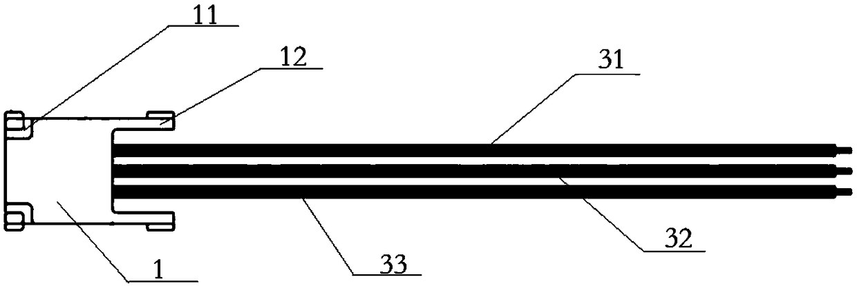
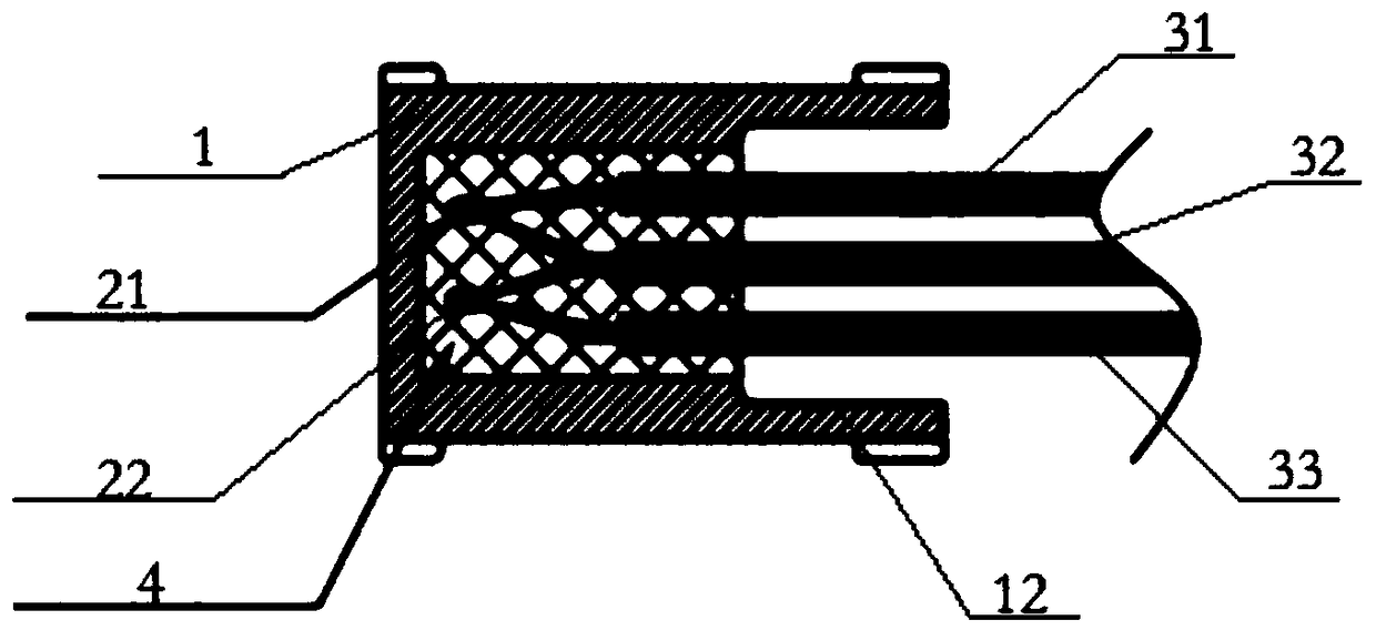
[0030] A temperature sensor with multiple thermistors, such as figure 1 As shown, it includes a shell 1, at least two thermistors and at least three wires, the pins of the thermistors are connected to each other to form a parallel relationship between the thermistors and the thermistors The pins are respectively connected to one end of the wires one by one, all the thermistors and the ends of the wires connected to the thermistors are wrapped in the casing, and the other ends of all the wires extend outside the casing, The shell is filled with epoxy resin 4 .

[0031] In this embodiment, more specifically, there are two thermistors, and the wires are three wires, and the two thermistors are respectively denoted as the first thermistor 21 and the second thermistor 22, and the three wires are respectively denoted as As the first wire 31, the second wire 32 and the third wire 33, the first pin of the first thermistor 21 is connected to the first wire 31, and the second pin of th...

Embodiment 2

[0035] A temperature sensor of multiple thermistors (not shown in the figure), including a shell, at least two thermistors and at least three wires, the pins of the thermistors are connected to each other to form a thermistor and the pins of the thermistor are respectively connected to one end of the wire in one-to-one correspondence, all thermistors and the ends of the wires connected to the thermistor are wrapped in the shell, all The other end of the wire extends outside the shell, and the shell is filled with epoxy resin.

[0036]When there are three thermistors, the wires are four wires, and the three thermistors are respectively denoted as the first thermistor, the second thermistor and the third thermistor, and the four wires are respectively denoted as the first thermistor. A wire, a second wire, a third wire and a fourth wire, the first pin of the first thermistor is connected to the first wire, and the second pin of the first thermistor is connected to the second the...

Embodiment 3

[0041] The power battery BMS device detection system based on the multi-thermistor temperature sensor of embodiment 1 and embodiment 2 is used to judge the temperature of the battery pack, including the above-mentioned multi-thermistor temperature sensor and battery BMS device, The wire of the temperature sensor is connected to the control system of the battery BMS device, the temperature sensor is connected to the battery pack for detecting the temperature signal of the battery pack, and the temperature sensor feeds back the temperature signal to the battery BMS device As the control system of the battery BMS device is equipped with a corresponding alarm prompt device, if one of the thermistors is abnormal, that is, there is a problem with the detection of one of the thermistors, then the temperature sensor will monitor the other thermistors. The temperature signal is fed back to the control system of the battery BMS device, and the corresponding alarm prompt device will issue...


PUM


Abstract

The invention discloses a multi-thermistor temperature sensor comprising a shell, at least two thermistors and at least three wires. The pins of the thermistors are connected to each other to form a mutual parallel relationship between the thermistors, and the pins of the thermistors are respectively connected to one end of the wires in a one-to-one correspondence. All the thermistors and all theends of wires connected with the thermistors are wrapped in the shell, and the other ends of all the wires extend outside the shell. The shell is filled with epoxy resin. According to the multi-thermistor temperature sensor and power battery BMS device detecting system, a plurality of thermistors are connected in parallel and then potted in the shell of the sensor for solidification, the same temperature collecting point is collected by several identical thermistors, the temperature information is feedback to the battery BMS device at the same time, so that the control system of the battery BMS device can automatically shield the abnormal data of the thermistors and make a prompt if one of the thermistors is abnormal, and normal driving of the vehicle will not be affected due to the presence of multiple thermistors.

Description

technical field [0001] The invention relates to the field of sensors, in particular to a multi-thermistor temperature sensor and a power battery BMS device detection system. Background technique [0002] In the existing power battery BMS system detection devices, SMD chip resistors are indirectly attached to the aluminum sheet to detect the temperature of each battery in the battery BMS system. When the traditional SMD chip resistors are used as temperature sensors for detection, And most of the existing temperature sensors are a sensitive element, which will lead to: due to the limitation of SMD chip resistance, the temperature measurement is inaccurate with a difference of 5-10°C; since there is only one sensitive element, once each battery in the battery BMS system If there is a problem, it is impossible to distinguish whether it is a battery problem or a temperature sensor problem; if the SMD chip resistor fails, it will cause dire consequences, and the battery may insta...

Claims


Application Information

Patent Timeline
Patent Type & Authority Applications(China)
IPC IPC(8): G01K7/22G01K1/08G01K1/14
CPCG01K1/08G01K1/14G01K7/22
Inventor 苗祥魁王剑
Owner 杭州科美特传感器有限公司
Features
  • R&D
  • Intellectual Property
  • Life Sciences
  • Materials
  • Tech Scout
  • Unparalleled Data Quality
  • Higher Quality Content
  • 60% Fewer Hallucinations
Learn More