
Method and device for detecting motor bearing failure

A technology for motor bearings and faults, which is applied in the direction of measuring devices, mechanical bearing testing, and testing of mechanical components, can solve problems such as difficult to accurately extract fault features, signal mode aliasing, nonlinearity, etc. Modal aliasing, the effect of improving accuracy

Inactive Publication Date: 2018-12-28
BEIJING INFORMATION SCI & TECH UNIV
View PDF5 Cites 3 Cited by
  • Summary
  • Abstract
  • Description
  • Claims
  • Application Information

AI Technical Summary

Problems solved by technology

When the motor bearing fault occurs, the complex working environment and working mechanism of the mechanical transmission motor make the harmonic signal of the bearing fault generally manifest as non-stationary and nonlinear, which makes it difficult to accurately extract the fault characteristics and the signal-to-noise ratio is low, which in turn affects the motor. Status recognition rate of bearing faults
Existing various fault diagnosis techniques (such as Empirical Mode Decomposition (EMD)) use the method of envelope calculation, which makes the signal components obtained by decomposition discontinuous. After multiple decompositions, the envelope estimation error is reduced by There is serious mode aliasing phenomenon in the amplified and decomposed signal, which leads to insufficient feature extraction
In addition, after feature extraction in different fault states, existing fault diagnosis techniques usually use binary classifiers such as support vector machines (SVM) and correlation vector machines (RVM) to identify fault states , so the existing various fault diagnosis technologies are relatively simple in identifying fault types, and it is difficult to accurately distinguish and identify minor faults and inherent defects of the motor

Method used


Image

  • Method and device for detecting motor bearing failure
  • Method and device for detecting motor bearing failure
  • Method and device for detecting motor bearing failure

Examples


Embodiment Construction

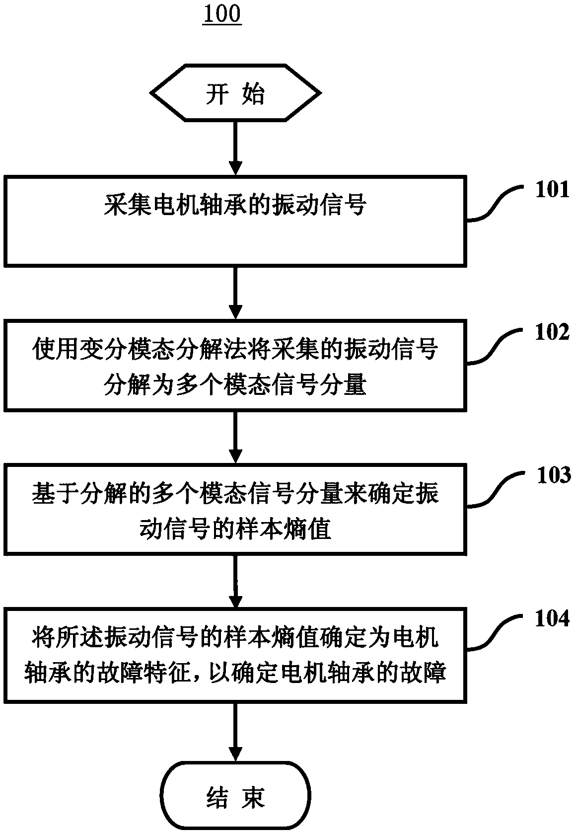
[0020] The idea of ​​the present invention is: first, the original input signal from the motor bearing is decomposed by using the variational mode decomposition method (VMD), and then an effective modal signal component is selected from the decomposed multiple modal signal components to calculate the original input signal The sample entropy value of the signal is determined, and the sample entropy value of the vibration signal is determined as the fault feature of the motor bearing, so as to determine the fault type of the motor bearing. Since the signal components decomposed by VMD are nonlinear and non-stationary, the complexity of the original input signal is effectively reduced. In addition, the problem of modal aliasing in the decomposed signal is effectively solved and effectively avoided. The occurrence of the endpoint effect. In addition, since the sample entropy value of the decomposed signal is used as the fault feature of the motor bearing, the extracted features ha...


PUM


Abstract

The invention provides a method and a device for detecting motor bearing failure. The method comprises the following steps of: collecting a vibration signal of the motor bearing; decomposing the collected vibration signal into a plurality of modal signal components by using a variational mode decomposition method; determining a sample entropy value of the vibration signal based on the decomposed plurality of modal signal components; and determining the sample entropy value of the vibration signal as a fault characteristic of the motor bearing to determine a fault type of the motor bearing. Thedevice comprises a signal collection unit, a signal decomposition unit, an entropy value determination unit, and a failure determination unit, wherein the signal collection unit collects the vibration signal of the motor bearing; the signal decomposition unit decomposes the collected vibration signal into a plurality of modal signal components by using a variational mode decomposition method; theentropy value determination unit determines the sample entropy value of the vibration signal based on the decomposed plurality of modal signal components; and the fault determination unit determinesthe sample entropy value of the vibration signal as the fault characteristic of the motor bearing to determine the fault type of the motor bearing.

Description

technical field [0001] The present application relates to the field of fault diagnosis, in particular to a method and device for detecting motor bearing faults based on variational mode decomposition (VMD), sample entropy and multi-classification correlation vector machines. Background technique [0002] In recent years, with the large-scale and complex development of modern machinery and equipment, the normal operation of equipment is of great significance to ensure the safety and efficiency of the manufacturing process. As the main drive equipment, the motor has become one of the indispensable parts of mechanical equipment or rotating system. Rolling bearings are the most important part of motors, and bearing failures account for about 50% of motor failures. Once a bearing failure occurs, it may lead to the shutdown of the entire production line, and even cause personal injury or death of the staff in severe cases. Therefore, it is of great significance to study the faul...

Claims


Application Information

Patent Timeline
Patent Type & Authority Applications(China)
IPC IPC(8): G01M13/04G06F17/14
CPCG01M13/045G06F17/14
Inventor 朱希安王占刚路照坭
Owner BEIJING INFORMATION SCI & TECH UNIV
Learn More