
Electromagnetic ejection system

A technology of electromagnetic ejection and electromagnetic coil, which is applied in the directions of educational appliances, instruments, teaching models, etc., can solve the problems of rigidity, complex model teaching aid system, and not easy to arouse students' interest.

Inactive Publication Date: 2018-12-28
FOSHAN UNIVERSITY
View PDF5 Cites 4 Cited by
  • Summary
  • Abstract
  • Description
  • Claims
  • Application Information

AI Technical Summary

Problems solved by technology

[0003] In order to let students better understand the working principle of electromagnetic guns, many schools have produced some model teaching aids, but the existing model teaching aids are complicated and rigid, and it is not easy to arouse students' interest.

Method used


Image

  • Electromagnetic ejection system
  • Electromagnetic ejection system

Examples


Embodiment 1

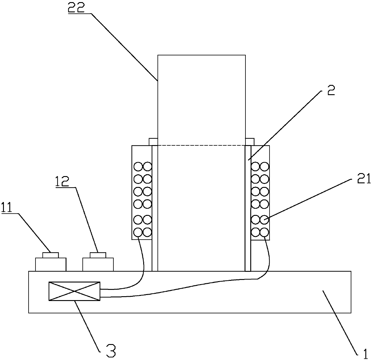
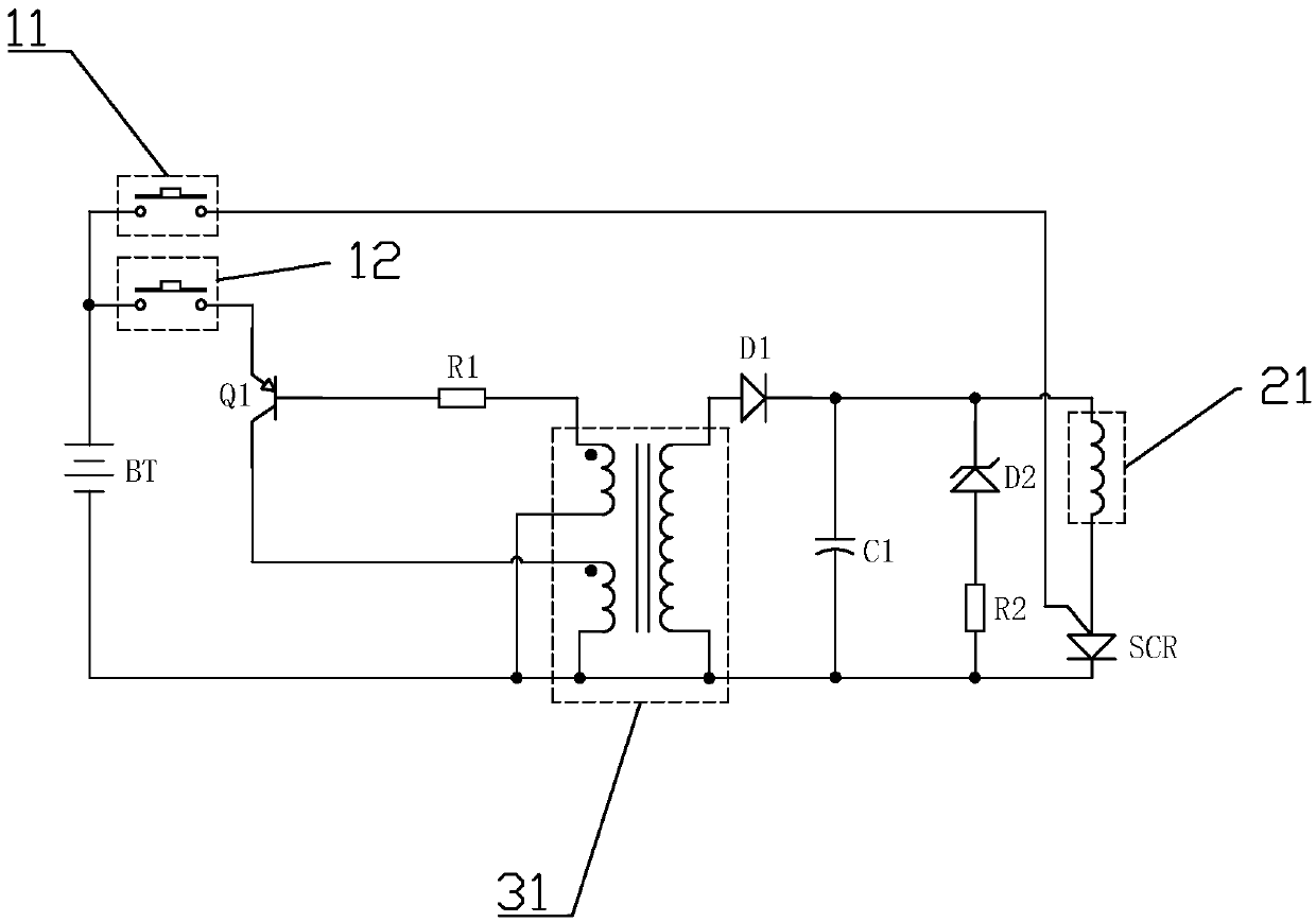
[0014] Embodiment 1, reference figure 1 with figure 2 , an electromagnetic ejection system, comprising: a base 1, a control circuit 3 is arranged in the base 1, a base tube 2, a first button 11 and a second button 12 are arranged on the base 1, the base The tube 2 is placed vertically, and the outer wall of the base tube 2 is wound with an electromagnetic coil 21. The control circuit 3 includes: a battery pack BT, a triode Q1, a first resistor R1, a second resistor R2, a transformer 31, a diode D1, an energy storage Capacitor C1, regulator tube D2, thyristor SCR, the transformer 31 is provided with a primary winding, a feedback winding, and a secondary winding, and the positive pole of the battery pack BT is connected to one end of the first button 11 and the second button 12 respectively. The other end of the first button 11 is connected to the control terminal of the silicon controlled rectifier SCR, the other end of the second button 12 is connected to the emitter of the ...


PUM


Abstract

The invention discloses an electromagnetic ejection system. The electromagnetic ejection system comprises a base, wherein the base is internally provided with a control circuit, the base is provided with a base tube, a first button and a second button, the base tube is internally disposed, an outer wall of the base tube is wound by an electromagnetic coil, the control circuit comprises a battery pack, a triode, a first resistor, a second resistor, a transformer, a diode, a storage capacitor, a voltage-regulator tube and a silicon controlled rectifier, the storage capacitor is charged through the second button, the silicon controlled rectifier is triggered through utilizing the first button, the storage capacitor is made to discharge electrical energy to an electromagnetic coil, and therebyejection of iron beads is completed. The electromagnetic ejection system is advantaged in that teaching in joy is achieved, students are helped to better understand the work principle of an electromagnetic gun, and the electromagnetic ejection system can be applied to teaching.

Description

technical field [0001] The invention relates to the technical field of model teaching aids, in particular to an electromagnetic ejection system. Background technique [0002] The force experienced by moving charges in a magnetic field is called Ampere's force, which is the force that a magnetic field exerts on moving charges. This principle is used in the military to manufacture electromagnetic guns. Electromagnetic guns have the advantages of fast firing rate and long range. At the same time, since gunpowder is not required, compared with gunpowder-launched shells, it can greatly save space and greatly reduce costs. [0003] In order to allow students to better understand the working principle of electromagnetic guns, many schools have produced some model teaching aids, but the existing model teaching aid systems are complicated and rigid, and it is not easy to arouse students' interest. Contents of the invention [0004] In order to solve the problems existing in the pr...

Claims


Application Information

Patent Timeline
Patent Type & Authority Applications(China)
IPC IPC(8): G09B23/18
CPCG09B23/181
Inventor 何三毛陈丹凤徐才睿周本腾刘明林杨健茂姜桂秀
Owner FOSHAN UNIVERSITY
Learn More