Testing device and method for determining minimum sprinkling flow density of spent fuel rod bundle

A test device and flow density technology, applied in the fields of nuclear reactor monitoring, reactors, nuclear power generation, etc., can solve the problem of inability to obtain the temperature of spent fuel rods, and achieve the effect of preventing radioactive accidents

Pending Publication Date: 2018-12-28
SHANGHAI NUCLEAR ENG RES & DESIGN INST CO LTD +1
View PDF0 Cites 1 Cited by
  • Summary
  • Abstract
  • Description
  • Claims
  • Application Information

AI Technical Summary

Problems solved by technology

Even if the flow density distribution of the spray cooling system in the area covered by the spent fuel pool can be obtained through experiments, it is impossible to obtain the corresponding spray cooling system for spent fuel assemblies with different discharge times from the core and thus different decay thermal power. The specific temperature that the spent fuel rod can reach under the flux density

Method used


Image

  • Testing device and method for determining minimum sprinkling flow density of spent fuel rod bundle

Examples


Embodiment Construction

[0031] In order to make the above objects, features and advantages of the present invention more comprehensible, the present invention will be further described in detail below in conjunction with the accompanying drawings and specific embodiments.

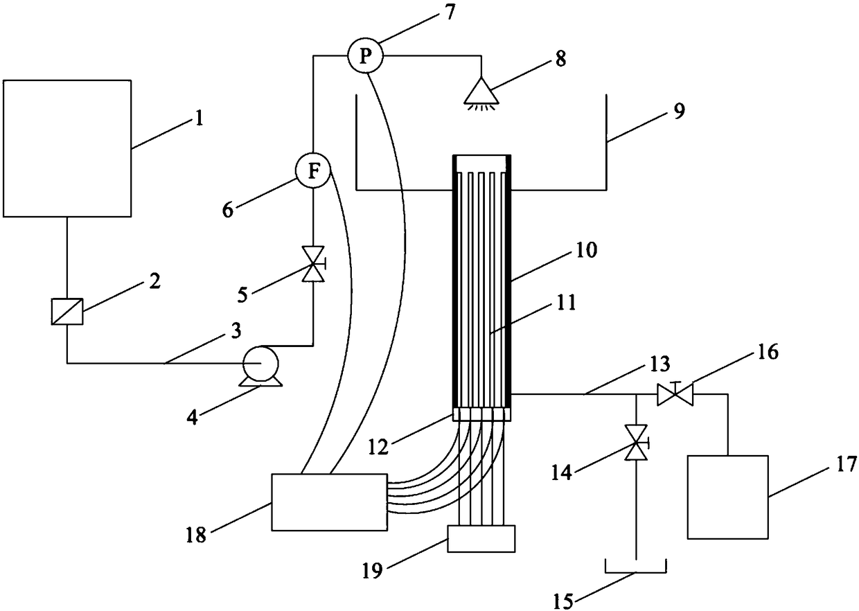
[0032] like figure 1 As shown, the test device for determining the minimum spray flow density of spent fuel bundles according to the present invention mainly includes:

[0033] A simulated spent fuel rod bundle 11 composed of 5×5 metal electric heating rods, heating wires are embedded in the metal rods, and the electric heating system 19 provides corresponding heating power for each metal rod to simulate different spent fuel rod decay heat power . Insulation 10 is arranged around the rod bundle, and a sealing structure 12 is arranged at the bottom to prevent the heat loss of the electric heating rod. The transparent enclosure 10 can also be used to prevent splashing of spray water and visual observation. The bottom of the enclos...


PUM


Abstract

The invention provides a testing device and a testing method for determining the minimum sprinkling flow density of a spent fuel rod bundle. The testing device comprises a simulated spent fuel rod bundle, a transparent insulation enclosure, a sealing structure, a water draining pipe, a sprinkling water supply pipe, a data acquisition and processing system and an electric heating system, wherein the transparent insulation enclosure is arranged on the periphery of the simulated spent fuel rod bundle; the sealing structure is arranged at the bottom of the simulated spent fuel rod bundle; the water draining pipe is arranged at the bottom of the enclosure; the water draining pipe is connected with a water draining tank and a water storage tank through a first water draining valve and a second water draining valve respectively; the sprinkling water supply pipe is used for supplying a cooling water source to the simulated spent fuel rod bundle; the data acquisition and processing system is used for acquiring and processing the sprinkling flow and the sprinkling pressure in the testing device and temperature data of heating rods; the electric heating system is used for providing corresponding heating power for metal electric heating rods. The invention further provides the testing method for determining the minimum sprinkling flow density of the spent fuel rod bundle. Through the testing device and the testing method, the minimum sprinkling flow density required for different decay heating power and temperature limits under a spent fuel rod bundle sprinkling cooling condition can be obtained conveniently and fast.

Description

technical field [0001] The invention relates to a test device and method for determining the minimum spray flow density of spent fuel rods. Background technique [0002] As a design precedent in the field of nuclear power, the spray cooling system for the spent fuel pool of the AP1000 third-generation pressurized water reactor nuclear power plant is used to deal with special conditions such as accidents beyond the design basis, such as aircraft crashes or terrorist attacks, where the spent fuel pool is damaged and the pool is emptied. At present, the design of the spray cooling system is based on the cooling water evaporation to take away the decay heat of the spent fuel assembly, and conservatively calculate the required spray flow and spray flow density (spray flow per unit area) of the entire spent fuel pool. Even if the flow density distribution of the spray cooling system in the area covered by the spent fuel pool can be obtained through experiments, it is impossible to...

Claims


Application Information

Patent Timeline
Patent Type & Authority Applications(China)
IPC IPC(8): G21C17/00G21C17/06
CPCG21C17/001G21C17/06Y02E30/30
Inventor 陈丽桂璐廷程会方苏夏施伟陆道纲曹琼王汉韩一丹黄若涛柴庆竹王芳
Owner SHANGHAI NUCLEAR ENG RES & DESIGN INST CO LTD
Why Eureka
Try Eureka