Frame-twisted wire end disconnection detection system
A technology of splicing and framing, which is applied in the field of wire breakage detection system at the end of splicing splices. and occlusion, to achieve the effect of long-term cost reduction
- Summary
- Abstract
- Description
- Claims
- Application Information
AI Technical Summary
Problems solved by technology
Method used
Image
Examples
Embodiment 1
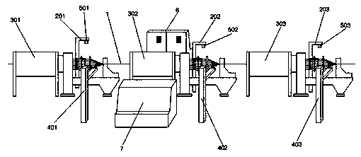
[0029] Such as figure 1 with figure 2 As shown, it includes frame twister, photoelectric sensor mechanism, proximity sensor mechanism, PLC electrical control box 6 and touch operation console 7. The photoelectric sensor mechanism is located on the side of the frame twister, and the photoelectric sensor mechanism is electrically controlled by PLC The box 6 and the touch operation console 7 are signal connected, and the detection end of the photoelectric sensor mechanism faces the winch of the frame winch and is located on the same horizontal plane as the winch. The proximity sensing mechanism is located on the side of the frame winch. The proximity sensing mechanism is connected to the PLC electrical control box 6 and the touch operation console 7 respectively. The detection end of the proximity sensing mechanism faces the winch of the frame winch and is located directly above the winch. . The frame stranding machine includes a first frame stranding machine 301, a second frame ...
Embodiment 2
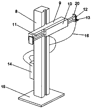
[0032] Based on Example 1, such as image 3 with Figure 4 As shown, the photoelectric sensor mechanism includes a column 8, a cross bar 9, a pneumatic unit 10, an air pump 14, and a photoelectric sensor 12. The cross bar 9 is arranged horizontally and connected to the column 8, and the cross bar 9 is provided with a pneumatic unit 10, the pneumatic unit 10 The power output end of the power output terminal is connected to the air pump 14 provided on the column 8. The pneumatic unit 10 is provided with a telescopic rod 11, one end of the telescopic rod 11 is provided with a push plate 20, and the photoelectric sensor 12 is located on the push plate 20. The push piece 20 has an "L"-shaped structure. A blowing nozzle 13 is provided on the horizontal section, and the blowing nozzle 13 is communicated with the air pump 14 through an air pipe 16, and the photoelectric sensor 12 is located on the vertical section of the push piece 20.
[0033] In use, compressed air is used to sweep thro...
Embodiment 3
[0035] Based on Example 2, such as Figure 5 As shown, the upper surface of the blowing nozzle 13 is an inclined downward slope, the upper surface of the blowing nozzle 13 is provided with an air outlet 17, and the blowing nozzle 13 is provided with an air cavity 19, which communicates with the air pipe 16 and the air outlet 17, respectively. An arc-shaped guide piece 18 is arranged in the blowing nozzle 13, and the arc-shaped guiding piece 18 is connected with the inner wall of the blowing nozzle 13, the top is flush with the air outlet 17, and the arc surface is concave upward.
[0036] In use, a mouthpiece equipped with an arc-shaped guide piece is provided, which can facilitate the direction of the blowing and greatly reduce the adhesion and shielding of dust such as aluminum powder. On the touch screen interface of the touch operation console, it includes the original set number of roots, the actual number of roots, the number of alarms per unit time, the number of zone alar...
PUM
 Abstract
Description
Claims
Application Information
 - R&D
- Intellectual Property
- Life Sciences
- Materials
- Tech Scout
- Unparalleled Data Quality
- Higher Quality Content
- 60% Fewer Hallucinations
Browse by: Latest US Patents, China's latest patents, Technical Efficacy Thesaurus, Application Domain, Technology Topic, Popular Technical Reports.
© 2025 PatSnap. All rights reserved.Legal|Privacy policy|Modern Slavery Act Transparency Statement|Sitemap|About US| Contact US: help@patsnap.com


