Synchronous signal control method and device

A technology of synchronization signal and control method, which is applied in the direction of synchronization device, wireless communication, electrical components, etc.

Active Publication Date: 2021-01-15
CHENGDU JINGWEI TECH CO LTD
View PDF9 Cites 0 Cited by
  • Summary
  • Abstract
  • Description
  • Claims
  • Application Information

AI Technical Summary

Problems solved by technology

[0004] In order to overcome the above-mentioned deficiencies in the prior art, the purpose of this application is to provide a synchronization signal control method and device to solve or improve the above-mentioned problems

Method used


Image

  • Synchronous signal control method and device
  • Synchronous signal control method and device
  • Synchronous signal control method and device

Examples


Embodiment Construction

[0039] The following will clearly and completely describe the technical solutions in the embodiments of the present application with reference to the drawings in the embodiments of the present application. Obviously, the described embodiments are part of the embodiments of the present application, not all of them. The components of the embodiments of the application generally described and illustrated in the figures herein may be arranged and designed in a variety of different configurations.

[0040] Accordingly, the following detailed description of the embodiments of the application provided in the accompanying drawings is not intended to limit the scope of the claimed application, but merely represents selected embodiments of the application. All other embodiments obtained by persons of ordinary skill in the art based on the embodiments in the present application without creative efforts shall fall within the protection scope of the present application.

[0041] It should ...


PUM


Abstract

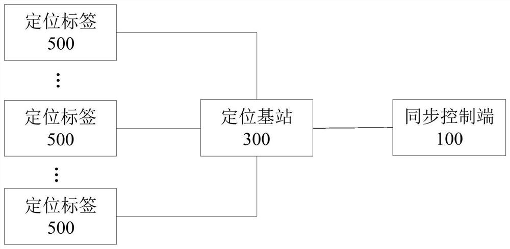
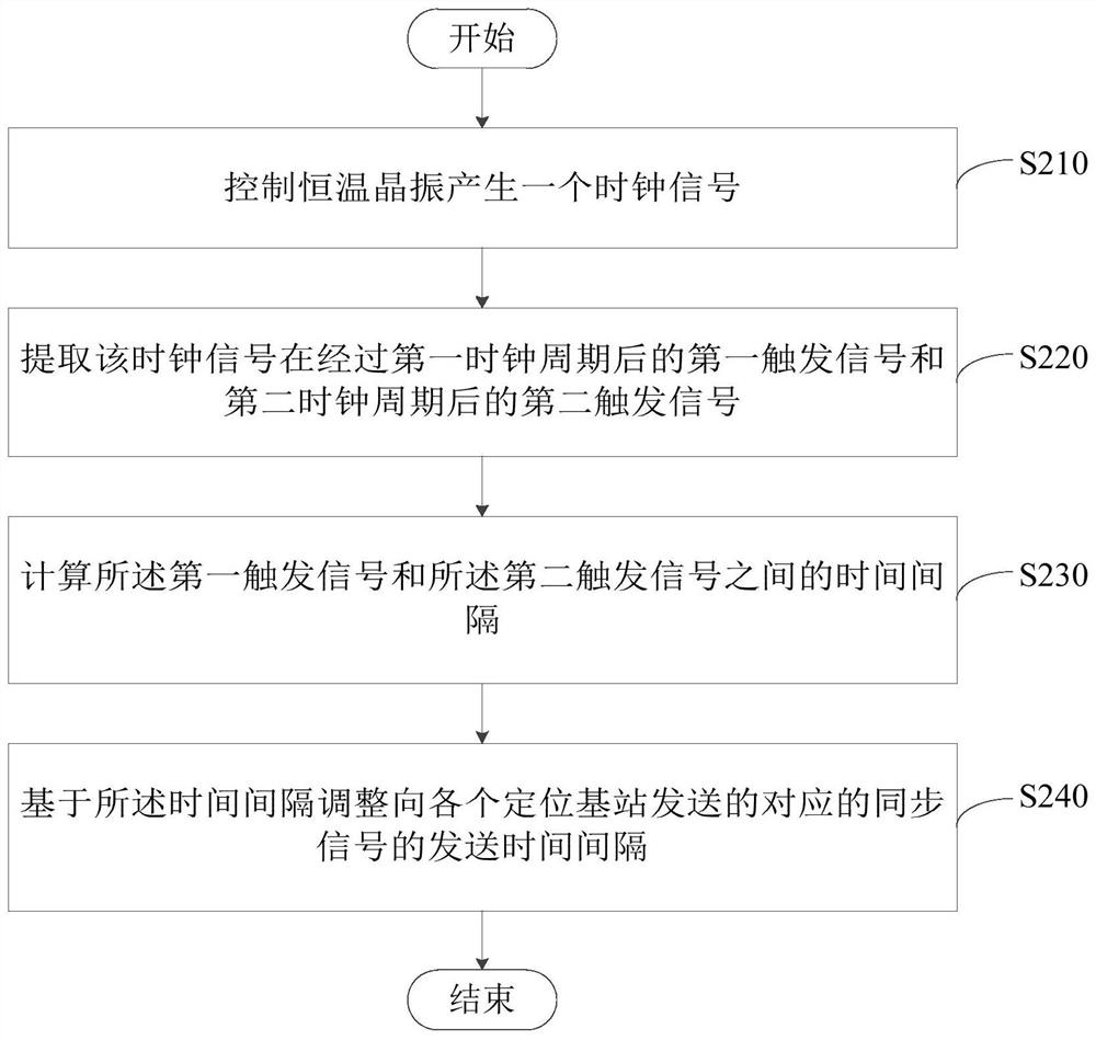
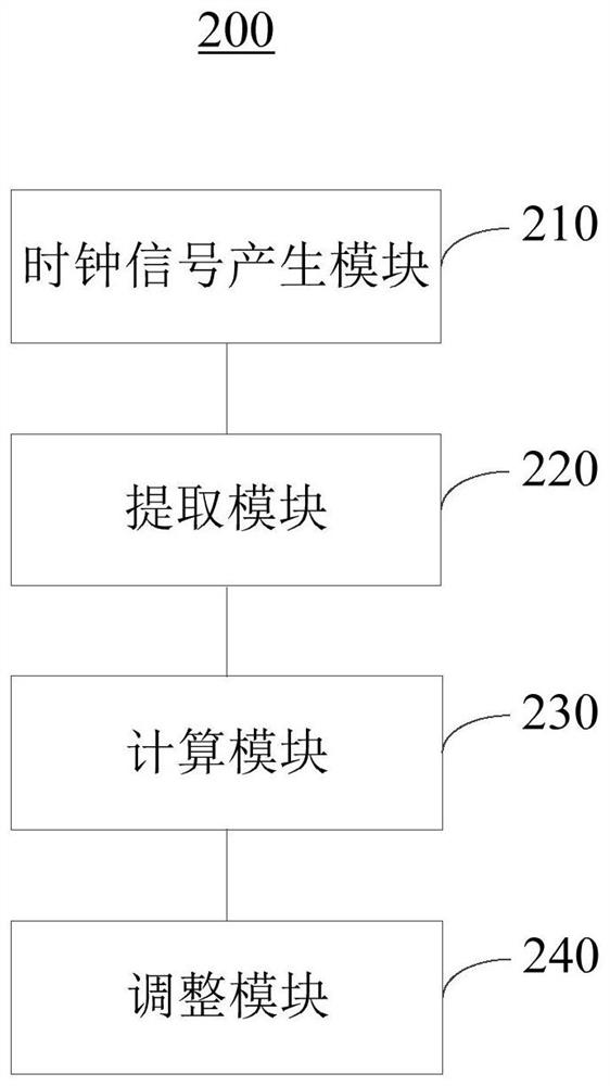
The embodiment of the present application provides a synchronization signal control method and a device, which are applied to a synchronization control terminal communicatively connected with each positioning base station. The present application generates a clock signal by controlling the isothermal crystal oscillator, and extracting a first trigger signal after a first clock cycle and a second trigger signal after a second clock cycle of the clock signal, wherein the second clock cycle is the next clock cycle of the first clock cycle, and then a time interval between the first trigger signaland the second trigger signal is calculated, and a transmission time interval of a corresponding synchronization signal transmitted to each positioning base station is adjusted based on the time interval. Therefore, by strictly controlling the interval time of each clock signal and strictly controlling the transmission time interval of the transmitted synchronization signal, the application can effectively reduce the delay error existing in the clock synchronization process between each positioning base station and the synchronization controller, achieve accurate synchronization, and make thepositioning work more stable.

Description

technical field [0001] The present application relates to the field of positioning technology, and in particular, to a synchronization signal control method and device. Background technique [0002] In the prior art, in an ultra wideband (Ultra Wideband, UWB) positioning system, clock synchronization needs to be performed on each positioning base station to improve positioning accuracy. However, each positioning base station often has a delay error in the process of clock synchronization with the synchronization controller. This delay error often leads to the cumulative error of subsequent synchronization signals, thereby seriously affecting the positioning accuracy. [0003] However, since in a positioning system, the positions of the positioning base stations are different, and the distance between the positioning base station and the synchronization control terminal is different, it is difficult to accurately determine how much the clock signal received by a positioning b...

Claims


Application Information

Patent Timeline
Patent Type & Authority Patents(China)
IPC IPC(8): H04W56/00
CPCH04W56/001H04W56/0045
Inventor 严炜严鸿谢虎尹湘凡
Owner CHENGDU JINGWEI TECH CO LTD
Why Eureka
Try Eureka