Lower die for machining drawer slide rail

A technology of molds and slide rails, which is applied in the direction of forming tools, manufacturing tools, metal processing equipment, etc., can solve the problems of time-consuming and power consumption, and low efficiency of processing slide rails

Active Publication Date: 2019-01-01
海宁市德亿金属制品股份有限公司
View PDF7 Cites 2 Cited by
  • Summary
  • Abstract
  • Description
  • Claims
  • Application Information

AI Technical Summary

Problems solved by technology

[0004] However, the above technical solutions are all distributed on different punching machines for processing, such processing consumes time and power, and the efficiency of processing slide rails is not high

Method used


Image

  • Lower die for machining drawer slide rail
  • Lower die for machining drawer slide rail
  • Lower die for machining drawer slide rail

Examples


Embodiment Construction

[0026] The following clearly and completely describes the technical solutions in the embodiments of the present invention. Obviously, the described embodiments are only some of the embodiments of the present invention, but not all of them. Based on the embodiments of the present invention, all other embodiments obtained by persons of ordinary skill in the art without making creative efforts belong to the protection scope of the present invention.

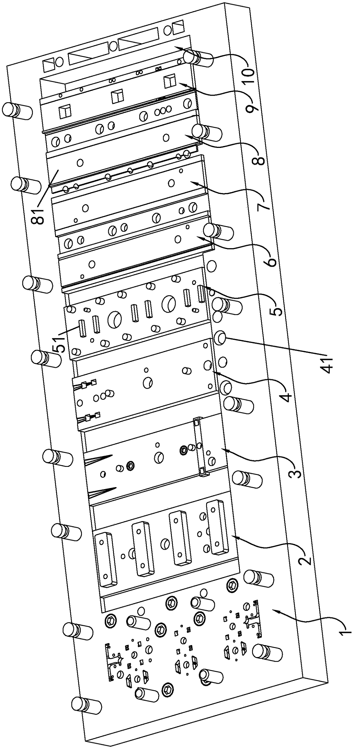
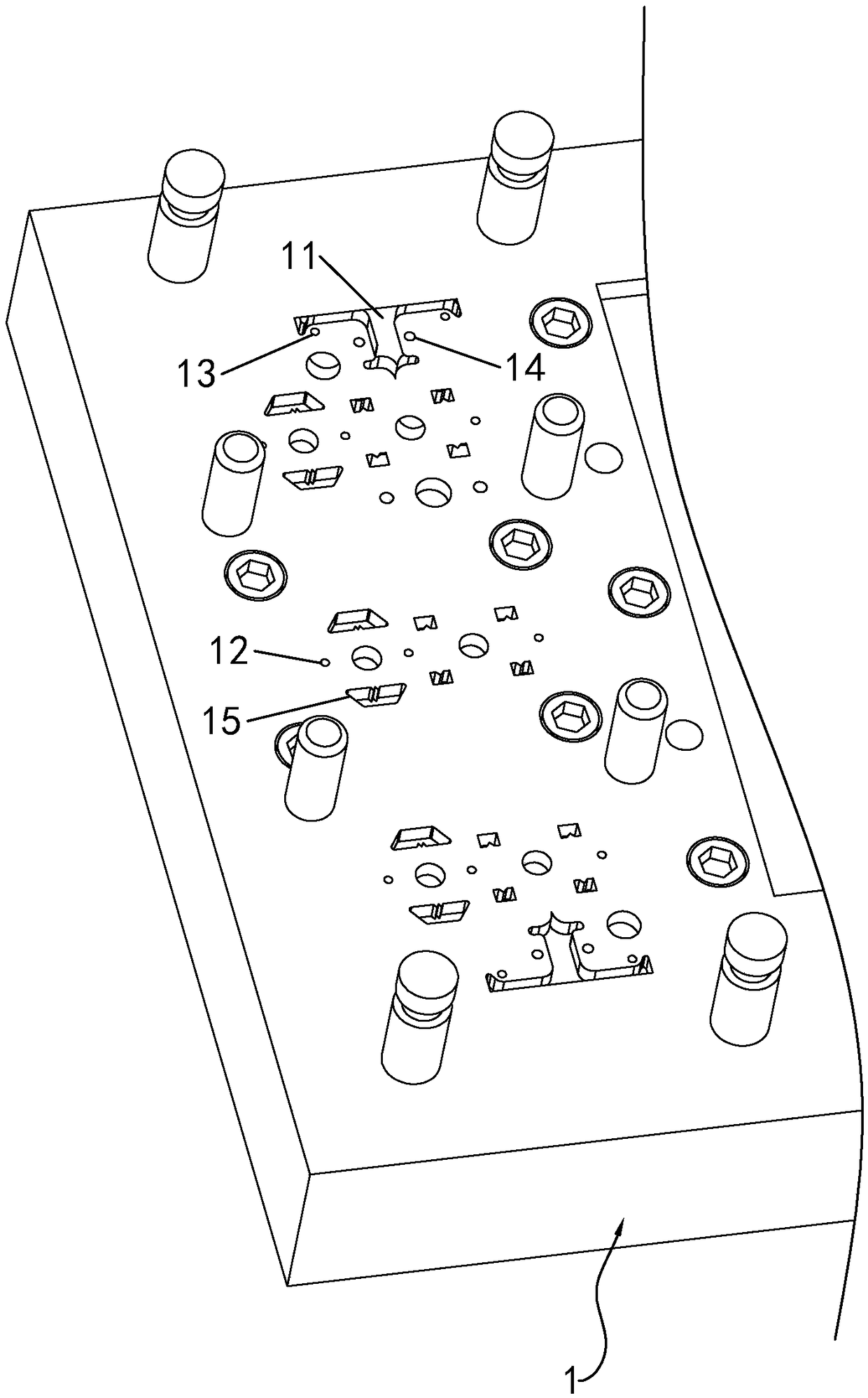
[0027] see Figures 1 to 8 , a lower mold for processing drawer slide rails, comprising a first lower mold 1, a T-shaped groove 11 for stamping and forming a T-shaped hole on both sides, a hole-groove 12 for stamping and forming a screw hole and Groove 2 13 is a guide wheel groove 14 for stamping and forming a guide wheel hole, and a trapezoidal groove 15 for stamping and forming a trapezoidal hole.

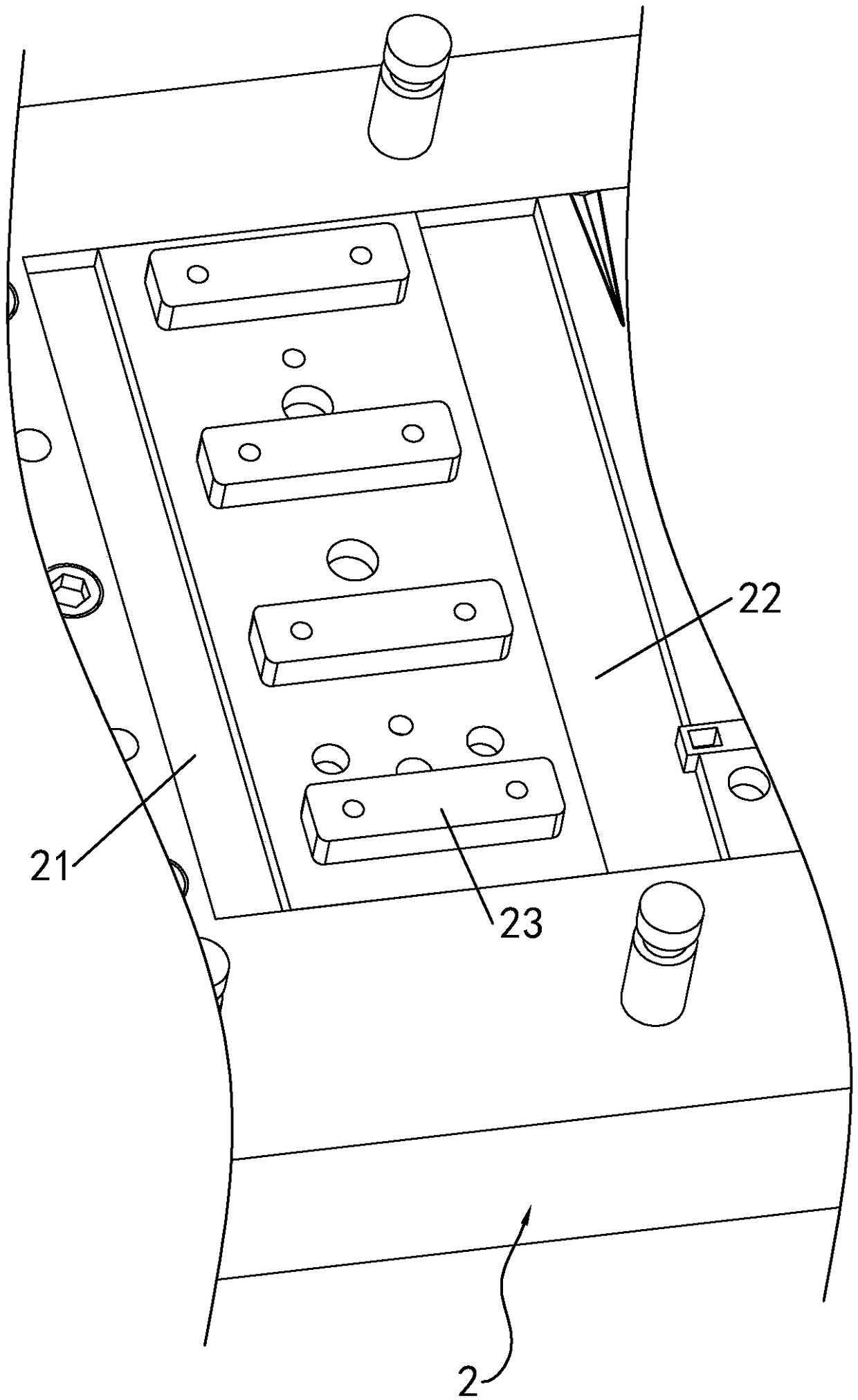
[0028] The second lower mold 2 has a first bending groove 21 formed between it and the first lower mold 1 , a second bending groove ...


PUM


Abstract

The invention relates to a lower die for machining a drawer slide rail. The lower die for machining the drawer slide rail comprises a first lower die body, a second lower die body, a third lower die body, a forth lower die body, a fifth lower die body, a sixth lower die body, a seventh lower die body, an eighth lower die body, a ninth lower die body and a tenth lower die body, wherein T-shaped grooves, first hole grooves, second hole grooves, guide wheel grooves and trapezoidal grooves are formed in the two edges of the first lower die body, a first bending groove, a second bending groove andfloating blocks are arranged on the second lower die body, drop-shaped groove extension parts are arranged on the third lower die body, annular grooves are formed in the rear end of the forth lower die body, the fifth lower die body is used for bending baffles with triangular teeth in trapezoidal holes, the sixth lower die body is used for forming a first floating plate with a 45-degree folded edge and a first blocking strip with an inclined surface, the seventh lower die body is used for forming a second floating plate with a 90-degree folded edge and a second blocking strip with a vertical surface, a third stop block used for turning over is arranged on the left side of the eighth lower die body, the front end of the third stop block gradually bulges upwards, and the outer side of the bulge forms an arc-shaped section. According to the lower die for machining the drawer slide rail, a punching machine is used for punching, and a steel strip is directly formed into a slide rail, so that time and electricity of the machining are saved, and the working efficiency is improved.

Description

technical field [0001] The invention relates to a lower mold for processing drawer slide rails, belonging to the technical field of sliding mechanisms. Background technique [0002] The traditional drawer slide rail usually includes a pair of slide rails respectively arranged on both sides of the bottom of the drawer. And sleeved in the vertical board, can slide along the vertical board. The mounting surface of the pull plate is tightly connected with the outer surface of the drawer, and the pull plate slides back and forth along the inner wall of the vertical plate to achieve the purpose of opening and closing the drawer. In the traditional processing method of drawer slide rails, the pull plates are usually processed in pairs. Cut out blanks with corresponding shapes and sizes on the raw materials, then put the blanks on the punching machine, punch out mounting holes on the mounting surface of the blanks according to the predetermined position, and then press and bend th...

Claims


Application Information

Patent Timeline
IPC IPC(8): B21D37/08
CPCB21D37/08
Inventor 邱伟良侯唤茂
Owner 海宁市德亿金属制品股份有限公司
Why Eureka
Try Eureka