

Method and apparatus for bainite blades
a technology of bainite blades and methods, applied in the field of bainite blade methods and apparatuses, can solve the problems of few manufacturers, none of which manufacture in the united states, and components that are not only expensive, and are susceptible to periods of inability to be used
- Summary
- Abstract
- Description
- Claims
- Application Information
AI Technical Summary
Benefits of technology
Problems solved by technology
Method used
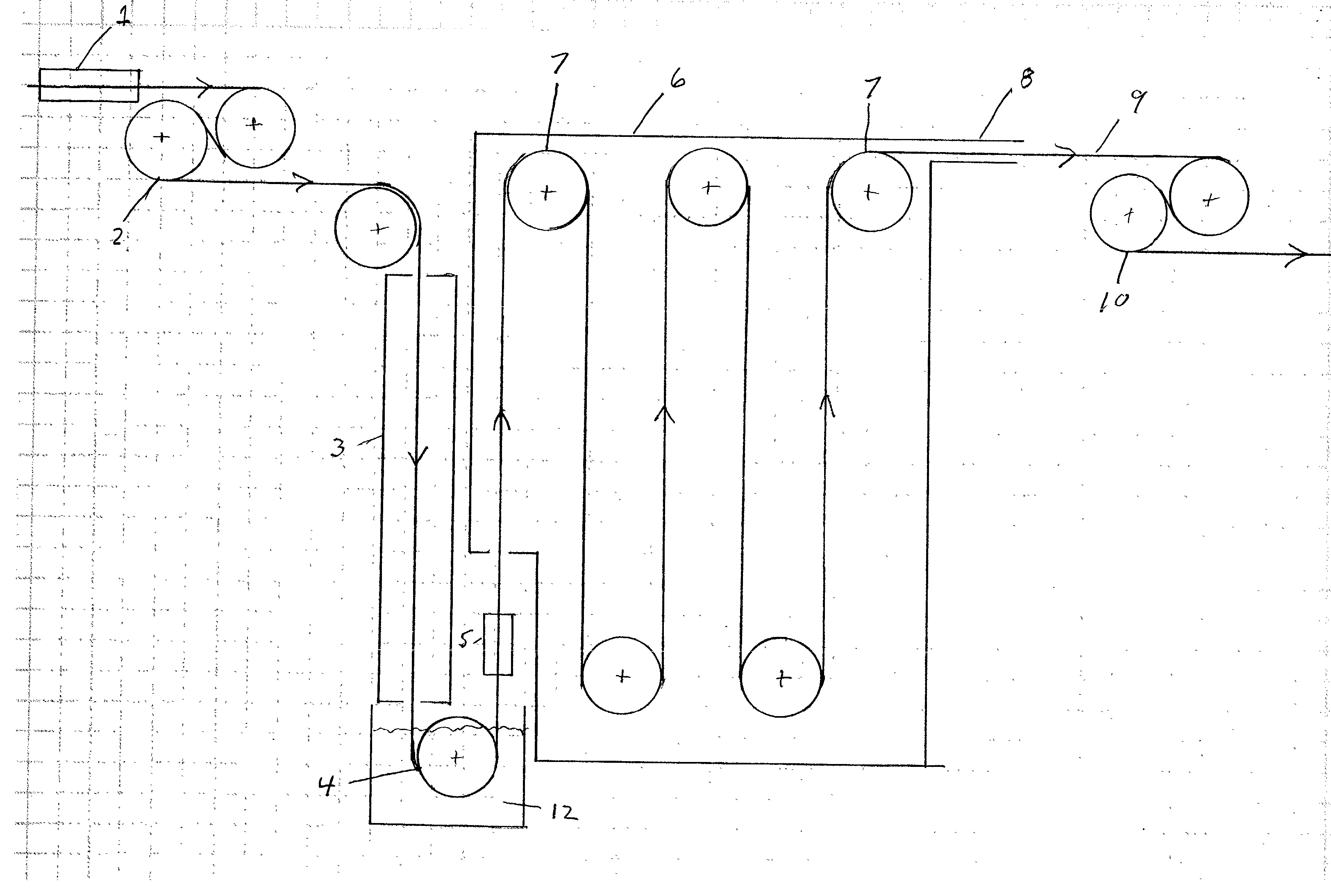
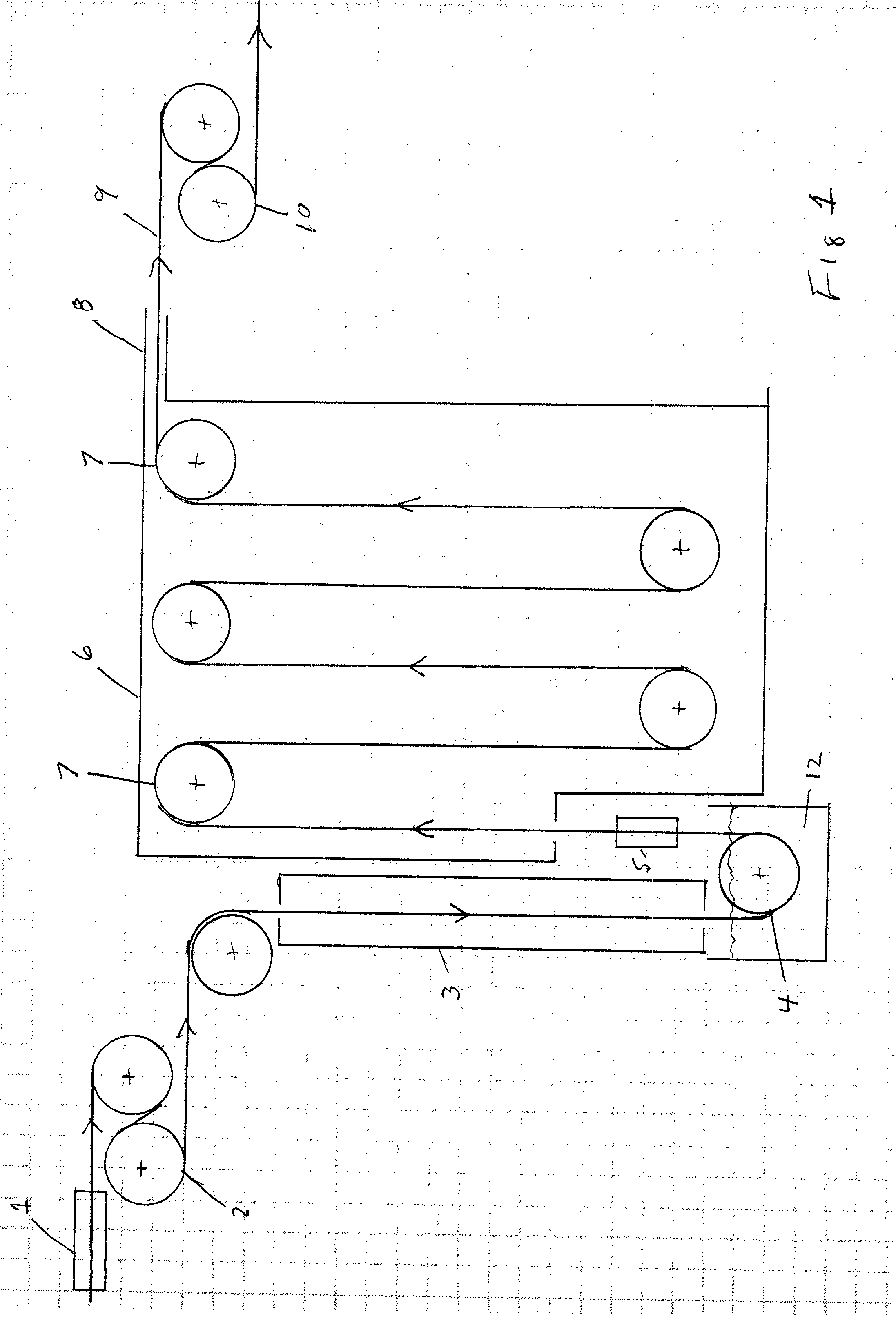
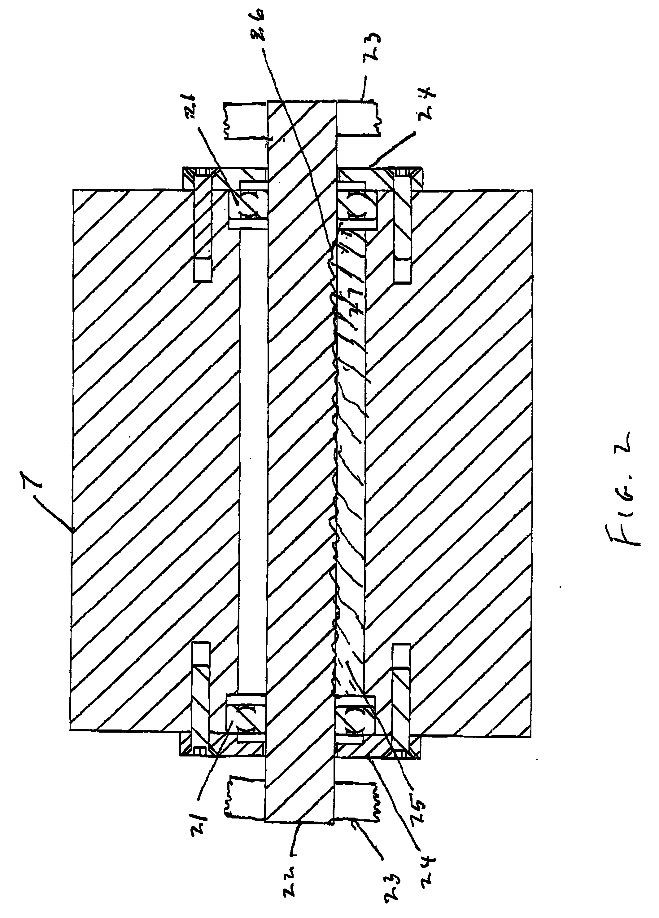
Image

Examples
Embodiment Construction
# START WT. GMS FINISH WT. GMS REMOVED WT. GMS WEAR RATE A1 Sandvik A-1 8.1903 8.0435 0.1468 0.0419 A2 1.25 C.3 Cr A-2 8.2508 8.1597 0.0911 0.0260 A3 1095 (Tiger) A-3 8.0455 7.9557 0.0898 0.0257 A4 Sandvik 400-8 6.0630 5.0747 0.9883 0.04297 A5 Microloy 400-9 6.0181 5.3879 0.6302 0.0274
[0101] Test runs A-1 through A-3 indicate an improved wear rate for the bainitic steel of up to 63%, runs A-4 through A-5 show an improved wear rate up to 56.8%.
[0102] Although these sample runs describe particular embodiments of the invention, many other variations and modifications and other uses may become apparent to those skilled in the art. It is preferred, that the present invention not be limited by this specific disclosure herein, but only by the appended claims.
PUM
| Property | Measurement | Unit |
|---|---|---|
| thicknesses | aaaaa | aaaaa |
| thicknesses | aaaaa | aaaaa |
| widths | aaaaa | aaaaa |
Abstract
Description
Claims
Application Information