
A multifunctional steel structure cutting and drilling device
A drilling device and steel structure technology, applied in the direction of manufacturing tools, other manufacturing equipment/tools, etc., can solve the problems of consuming manpower and material resources, low work efficiency, etc., and achieve the effect of improving work efficiency and saving manpower and material resources
- Summary
- Abstract
- Description
- Claims
- Application Information
AI Technical Summary
Problems solved by technology
Method used
Image

Examples
Embodiment Construction
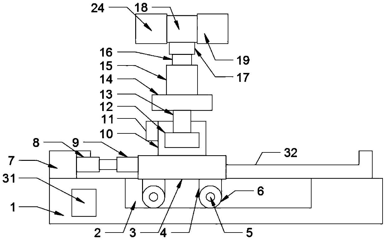
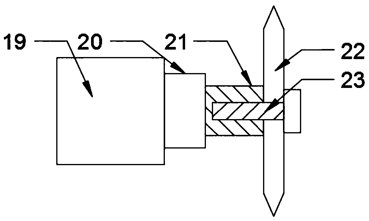
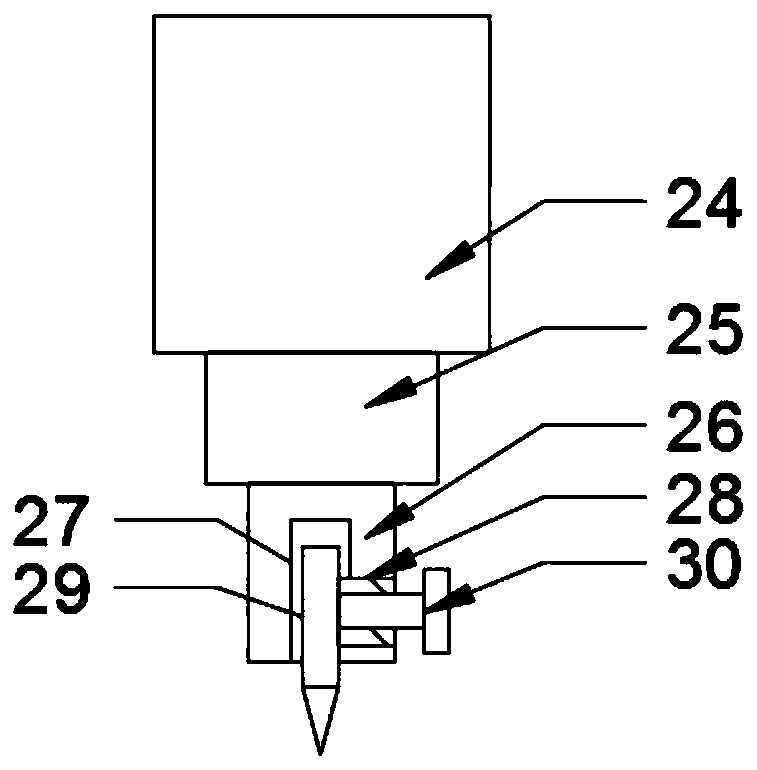
[0021] The present invention is specifically described below in conjunction with accompanying drawing, as Figure 1-5 As shown, a multifunctional steel structure cutting and drilling device includes a workbench body 1, the workbench body 1 is fixedly installed on the ground, and the workbench body 1 is provided with a cutting and drilling mobile lifting device. The mobile lifting device for cutting and drilling consists of a groove 2 fixed on the front end of the upper surface of the workbench body 1, a mobile base 3 located on the upper surface of the workbench body 1 and at the upper end of the groove 2, and a multi-layer fixedly mounted on the lower surface of the mobile base 3. A roller fixing frame 4, a roller shaft 5 inserted in the roller fixing frame 4, a roller 6 set in the roller shaft 5 and located on the upper surface of the groove 2, fixedly installed on the upper surface of the workbench body 1 and located in the groove 2 The linear motor 7 on one side, the teles...
PUM
 Abstract
Description
Claims
Application Information