Automatic batching machine for building construction

A technology for automatic batching and construction, which is applied to clay preparation devices, chemical instruments and methods, cement mixing devices, etc., and can solve the problems of difficulty in cleaning batching machines, splashing of internal mixtures, and lack of sealing devices at the discharge outlet. Safe and convenient, high mixing efficiency, scientific and reasonable structure

Inactive Publication Date: 2019-01-01
宁波恒鼎建设有限公司
View PDF2 Cites 1 Cited by
  • Summary
  • Abstract
  • Description
  • Claims
  • Application Information

AI Technical Summary

Problems solved by technology

[0004] The object of the present invention is to provide a kind of automatic batching machine for building construction, to solve the existing automatic batching machine proposed in the above-mentioned background technology usually share one feed port and discharge port, or lack a good feed port at its discharge port. The sealing device is easy to cause the splash of the internal mixture, and causes the problem that the batching machine is difficult to clean

Method used


Image

  • Automatic batching machine for building construction
  • Automatic batching machine for building construction
  • Automatic batching machine for building construction

Examples


Embodiment 1

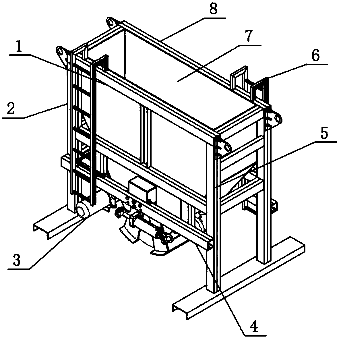
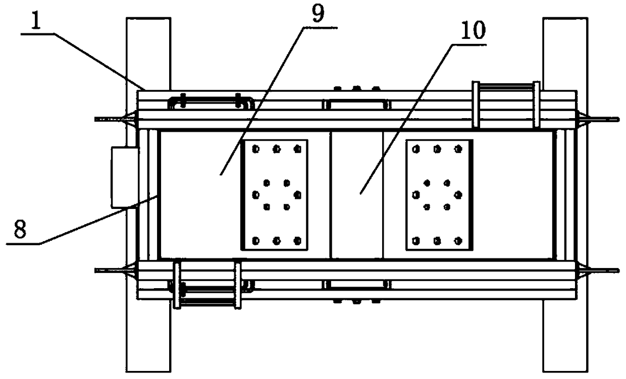
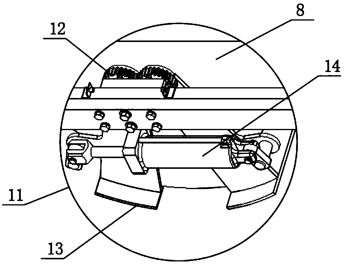
[0019] see figure 1 , figure 2 , image 3 , Figure 4 and Figure 5 , the present invention provides a technical solution: an automatic batching machine for building construction, including a frame 1 and a batching cabinet 8 fixed on the frame 1 by bolts, and escalators A2 are fixed on both sides of the frame 1 by bolts And the escalator B6 is convenient for the staff or maintenance personnel to clean and overhaul the batching cabinet 8, or check the operation of the machine; the frame 1 includes four columns 5 arranged in a rectangle and multiple columns fixed between the columns 5 Crossbar 4; the top of batching cabinet 8 is material inlet 7, and its bottom is discharge port 10, and the inside of batching cabinet 8 is the batching warehouse 9 that is communicated with feed inlet 7 and discharge port 10 respectively; The bottom end is an arc-shaped structure, and the drive motor 3 is respectively fixed by bolts on both sides thereof; the sealing mechanism 11 is fixed by ...

Embodiment 2

[0025] see figure 1 , figure 2 , image 3 , Figure 4 and Figure 5 , the present invention provides a technical solution: an automatic batching machine for building construction, including a frame 1 and a batching cabinet 8 fixed on the frame 1 by bolts, and escalators A2 are fixed on both sides of the frame 1 by bolts And the escalator B6 is convenient for staff or maintenance personnel to clean and overhaul the batching cabinet 8, or check the operation of the machine; the frame 1 includes four columns 5 arranged in a rectangle and multiple columns fixed between the columns 5 by welding root cross bar 4; the top of batching cabinet 8 is material inlet 7, and its bottom is discharge port 10, and the inside of batching cabinet 8 is the batching warehouse 9 that is communicated with feed inlet 7 and discharge port 10 respectively; The bottom end of 8 is an arc structure, and the drive motor 3 is respectively fixed by bolts on both sides thereof; the sealing mechanism 11 i...


PUM


Abstract

The invention discloses an automatic batching machine for building construction. The automatic batching machine comprises a rack and a batching case fixed on the rack, wherein a ladder A and a ladderB are respectively fixed at the two side faces of the rack; the rack comprises four stand columns which are distributed in a rectangle, and a plurality of cross bars fixed among the stand columns; a feeding hole is formed in the top end of the batching case, and a discharge hole is formed in the bottom end of the batching case; the batching case is internally provided with a distributing bin whichis separately communicated with the feeding hole and the discharge hole; the bottom end of the batching case has an arc-shaped structure, and drive motors are respectively fixed on the two side facesof the batching case; a sealing mechanism is fixed on the cross bar close to the discharge hole. The automatic batching machine is scientific and reasonable, safe and convenient to use, full in mixing and high in mixing efficiency; a hydraulic cylinder drives a movable sealing door so as to facilitate the blockage of the discharge hole and the opening for taking materials; furthermore, the sealing door is full in sealing, convenient to clean and long in service life.

Description

technical field [0001] The invention belongs to the technical field of building construction auxiliary machinery, and in particular relates to an automatic batching machine for building construction. Background technique [0002] The automatic batching machine is a machine that mixes cement, sand and gravel aggregates and water and mixes them into concrete mixtures. It mainly consists of a mixing drum, feeding and unloading mechanism, water supply system, prime mover, transmission mechanism, frame and supporting device Composition; according to the nature of work, it can be divided into batch type (batch type) and continuous type; according to the principle of stirring, it can be divided into self-falling type and forced type; according to the installation method, it can be divided into fixed type and mobile type; According to the structure of the mixing drum, it can be divided into pear type, drum type, double cone type, disc vertical shaft type and circular groove horizont...

Claims


Application Information

Patent Timeline
Patent Type & Authority Applications(China)
IPC IPC(8): B28C5/08
CPCB28C5/0806B28C5/0818
Inventor 何力权李剑张婷袁争光
Owner 宁波恒鼎建设有限公司
Why Eureka
Try Eureka