Anti-freezing system for roads and bridges

A highway bridge and anti-icing technology, applied in bridges, bridge parts, bridge construction, etc., can solve serious accidents, low freezing efficiency and other problems, achieve long service life, improve deicing effect, and reduce the possibility Effect

Inactive Publication Date: 2019-01-01
贵州省遵义公路管理局
View PDF7 Cites 2 Cited by
  • Summary
  • Abstract
  • Description
  • Claims
  • Application Information

AI Technical Summary

Problems solved by technology

Especially above bridges, once an accident occurs due to icing, it is easy to cause serious accidents, which requires the invention of a road deicing system
[0003] A Chinese patent (publication number: CN 106522088 B, announcement date: 2018.08.21) discloses an anti-freezing system for highway bridges, but in actual use, the anti-freezing system for highway bridges provided by the above documents The advantage of the system is that the invention is suitable for the installation of bridges with different lengths, improves the installation speed of the anti-freezing system, enables the anti-freezing system to have the function of utilizing solar energy, saves the energy consumption of the anti-freezing system when heating the bridge, and is environmentally friendly. The reason is that the efficiency of freezing is not high. Starting from destroying the conditions of freezing, destroying the conditions of freezing can prevent freezing. Therefore, it is necessary to invent an anti-freezing system for highway bridges.

Method used


Image

  • Anti-freezing system for roads and bridges
  • Anti-freezing system for roads and bridges
  • Anti-freezing system for roads and bridges

Examples


Embodiment 1

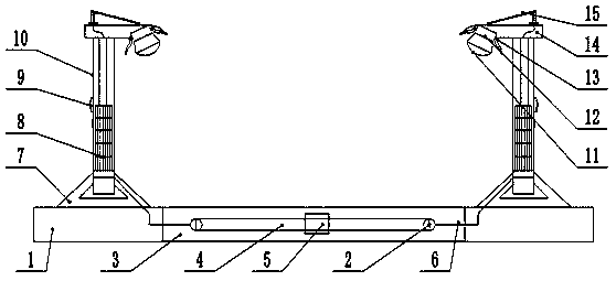
[0021] see figure 1 , an anti-freezing system for highway bridges, comprising: a street lamp support base 1, a roadbed 3, a support base 7, a street lamp column 10 and an installation platform 14, the roadbed 3 is the road above the bridge, and the two sides of the roadbed 3 A street lamp support base 1 is provided, and a support base 7 is fixedly installed on the top of the street lamp support base 1. The middle part of the support base 7 is fixedly installed with a street lamp column 10 through Luo Shuanggroup. The street lamp column 10 adopts angle steel as a frame, and the surface is fixed Steel plates are installed, and the surface is coated with antirust paint. The upper end of the street lamp column 10 is fixedly installed with an installation platform 14, and the upper end of the installation platform 14 is provided with a solar panel 15. The solar panel 15 adopts an inclined design, facing the sun's inclination direction, wherein the height of the rear support frame c...

Embodiment 2

[0024] Further, the support seat 7 adopts a triangular structure, which has strong stability and improves the stability of the street lamp.


PUM


Abstract

The invention discloses an anti-freezing system for roads and bridges and belongs to the field of road maintenance. The anti-freezing system comprises a street lamp supporting seat, a subgrade, a supporting seat, a street lamp stand column and a mounting platform, wherein a solar panel is arranged at the upper end of the mounting platform; a lamp holder is fixedly mounted at the front end of the mounting platform; a fixed supporting block is arranged in the middle of the subgrade; a steel product supporting beam is arranged at the lower end of the subgrade; the subgrade is internally providedwith a plurality of water collection channels which are uniformly distributed; the water collection channels are mutually communicated; an anti-slipping layer is arranged on the surface of the subgrade; a water accumulation opening is formed in the supporting block. Two sides of the anti-slipping layer are obliquely arranged and an inclined angle is 5 to 8 degrees, and water flow on a bridge deckis collected into the water collection channels and then is discharged; an inclined anti-slipping layer design and a channel design of the water collection channels are adopted and the water flow on the surface can be rapidly and efficiently drained, so that the probability that the bridge deck is frozen is greatly reduced; the deicing effect of the system is improved; the anti-freezing system hasthe advantages of simple and reliable structure, energy saving and environment protection and no consumption of energy sources.

Description

technical field [0001] The invention relates to the field of highway maintenance, in particular to an anti-freezing system for highway bridges. Background technique [0002] Road icing tends to occur during the period from November to April of the following year (that is, winter and early spring). In northern China, especially in the Northeast and northern Inner Mongolia, roads often freeze. In southern China, snowfall is generally "wet snow", which often belongs to mixed water at 0-4°C, and it will become ice-water paste when it hits the ground. When the temperature drops at night, it will solidify into large pieces of ice. As long as the local winter If the minimum temperature is lower than 0°C, there may be ice on the road. As long as the temperature does not rise enough to thaw the ice, it will remain rock-solid. Generally speaking, in the twelfth lunar month of winter, when there is a large-scale strong cold air activity that causes the temperature to drop (called a c...

Claims


Application Information

Patent Timeline
Patent Type & Authority Applications(China)
IPC IPC(8): E01C11/26E01D19/00
CPCE01C11/26E01D19/00Y02A30/60
Inventor 韩碧进梁旭之刘斌黄吉国郑世伦
Owner 贵州省遵义公路管理局
Why Eureka
Try Eureka