Tower-beam thrust connection device and self-anchored suspension bridge rapid construction method

A technology of self-anchored suspension bridges and connecting devices, which is applied in bridge construction, bridges, buildings, etc., can solve the problems of long construction period and difficult synchronous construction of self-anchored suspension bridges, so as to reduce construction costs, save on-site operation time, and resist The effect of high push stiffness

Active Publication Date: 2019-01-01
CHANGAN UNIV
View PDF13 Cites 2 Cited by
  • Summary
  • Abstract
  • Description
  • Claims
  • Application Information

AI Technical Summary

Problems solved by technology

[0010] In view of the deficiencies in the prior art, the purpose of the present invention is to provide a tower-beam thrust connection device and a rapid construction method for self-anchored suspension bridges, so as to solve the problem that the self-anchored suspension bridges in the prior art are difficult to construct synchronously and have a long construction period. technical issues

Method used


Image

  • Tower-beam thrust connection device and self-anchored suspension bridge rapid construction method
  • Tower-beam thrust connection device and self-anchored suspension bridge rapid construction method
  • Tower-beam thrust connection device and self-anchored suspension bridge rapid construction method

Examples


Embodiment 1

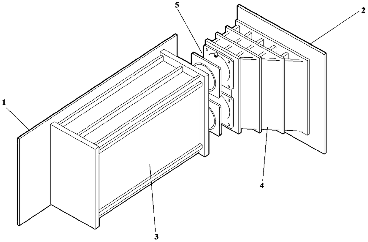
[0065] This embodiment provides a tower beam thrust connection device, such as Figure 1 to Figure 5 As shown, it includes the reserved steel plate 1 at the beam end and the bearing steel plate 2 at the tower end. There is a beam end thruster 3, a tower end thruster 4 is fixedly installed on the tower end pressure steel plate 2, and a thrust conductor 5 is arranged between the beam end thruster 3 and the tower end thruster 4;

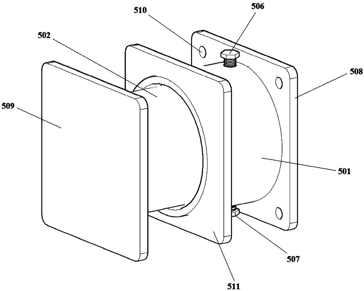
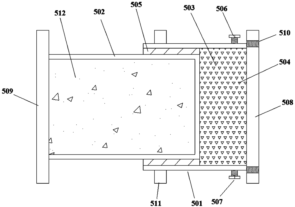
[0066] The thrust conductor 5 includes an outer cylinder 501 and an inner cylinder 502, one end of the outer cylinder 501 is open, and both ends of the inner cylinder 502 are closed, and the closed end of the outer cylinder 501 is installed on the tower end thruster 4, one end of the inner cylinder 502 is installed on the beam end thruster 3, and the other end of the inner cylinder 502 is inserted into the open end of the outer cylinder 501 so that a sand cavity 503 is formed in the outer cylinder 501, and the sand cavity 503 is filled with sand grains ...

Embodiment 2

[0077] This embodiment provides a kind of self-anchored suspension bridge rapid construction construction method, such as Image 6 with Figure 7 As shown, the method adopts the tower beam thrust connection device described in Embodiment 1. The method includes the following steps:

[0078] Step 1, synchronous construction of side span main girder 6 and bridge tower 7;

[0079] Step 1.1, carry out foundation treatment to the foundation of bridge tower 7 and bridge pier 12, construct bridge tower 7 foundation, bridge pier 12 foundation, bridge tower 7 and bridge pier 12;

[0080] Step 1.2, set up the anchor span prestressed concrete main beam and the bracket 11 required for the installation of the side mid span main beam, cast the anchor span concrete beam section on the bracket 11, stretch the prestressed steel beam, and complete the construction of the anchor span main beam;

[0081] Step 1.3, erecting the side-span main girder 6 section by section on the support 11, pourin...


PUM


Abstract

The invention provides a tower-beam thrust connection device and a self-anchored suspension bridge rapid construction method. The beam end resistor is fixedly installed on the beam end reserved steelplate in the tower beam thrust connection device, the tower end resistor is fixedly installed on the tower end pressure-bearing steel plate, and the beam end resistor is connected with the tower end resistor through a thrust conductor. The method comprises the following steps: step 1, synchronously constructing the main girder and the bridge tower of the side span; step 2, installing a tower-beamthrust connection device to temporarily connect the main girder of the side span with the bridge tower; step 3, synchronously constructing the main cable erection and the main beam installation; step4, detaching the tower beam thrust connection device to complete the first system conversion; step 5, pulling the boom, removing the bracket, and completing the second system conversion. The method ofthe invention adopts the tower beam thrust connection device to realize the cooperative installation of the main cable and the main beam safely and economically, thereby greatly saving the field operation time; Its characteristic is to increase the system conversion of the main girder by one time compared with the traditional process.

Description

technical field [0001] The invention belongs to the field of roads and bridges, and relates to a self-anchored suspension bridge, in particular to a tower-beam thrust connection device and a rapid construction method for a self-anchored suspension bridge. Background technique [0002] The self-anchored suspension bridge is different from the general ground-anchored suspension bridge. It does not require huge anchors. The main cable is anchored at the end of the main girder of the side span. The main girder bears the horizontal and vertical components of the main cable, which solves the geological problem. Conditions do not allow the construction of anchorage and the problem of building a suspension bridge, and retains the graceful shape of the traditional suspension bridge. [0003] Since the main cable of the self-anchored suspension bridge is directly anchored on the main girder, the main cable will generate a huge horizontal component force during the construction process...

Claims


Application Information

Patent Timeline
Patent Type & Authority Applications(China)
IPC IPC(8): E01D21/00
CPCE01D21/00
Inventor 王晓明邓耀白云腾贺耀北王欢茅相源金蝶汤圣鹏舒鹏
Owner CHANGAN UNIV
Why Eureka
Try Eureka