Multifunctional engraving, punching and cutting all-in-one machine

An all-in-one machine and multi-functional technology, applied in metal processing machinery parts, other manufacturing equipment/tools, metal processing, etc., can solve complex process problems, improve precision and efficiency, save space occupied by equipment, and avoid cuts The effect of the brace

An all-in-one machine and multi-functional technology, applied in metal processing machinery parts, other manufacturing equipment/tools, metal processing, etc., can solve complex process problems, improve precision and efficiency, save space occupied by equipment, and avoid cuts The effect of the brace

CN102554622AInactive Publication Date: 2012-07-11SHANDONG RUIJIE LIGHTING EQUIP

Image

  • Multifunctional engraving, punching and cutting all-in-one machine
  • Multifunctional engraving, punching and cutting all-in-one machine
  • Multifunctional engraving, punching and cutting all-in-one machine

Examples


Embodiment Construction

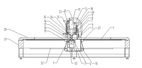
[0029] Examples such as figure 1 As shown, the all-in-one machine for engraving, punching and cutting includes a frame 21, a tackle 15 that can slide forward and backward is installed on the frame 21, and a machine head 2 that can move left and right is installed on the tackle 15. A punching device, a plasma cutting device and an engraving device are installed on the machine head 2 .

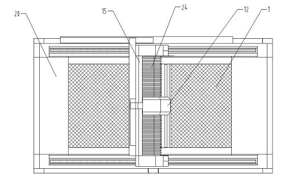
[0030] The upper part of the frame 21 is provided with a transmission net bag 1, the front and rear ends of the transmission net bag 1 are respectively fixedly connected with the frame 21, and the front end of the lower part of the trolley 15 is provided with two front supporting drive rollers arranged up and down. 27. The rear end is provided with two rear support drive rollers 19 arranged up and down, and the middle part of the conveying mesh bag 1 is staggered around the two front support drive rollers 27 and the two rear support drive rollers 19 and connected with the two front support drive...


PUM


Abstract

The invention discloses a multifunctional engraving, punching and cutting all-in-one machine, which comprises a framework. A pulley capable of sliding back and forth is mounted on the framework, a head capable of moving left and right is mounted on the pulley, and a punching device, a plasma cutting device and an engraving device are mounted on the head. The multifunctional engraving, punching and cutting all-in-one machine not only has functions of an engraving machine, but also has functions of a punching machine and functions of a plasma cutting machine, and is fast in machining speed, production efficiency is greatly improved, machining precision is enhanced, and production cost is saved.

Description

technical field [0001] The invention relates to an engraving machine, in particular to an engraving, punching and cutting multifunctional integrated machine suitable for punching LED characters in the advertising industry and iron sheet punching and cutting in the machining industry. Background technique [0002] Now whether it is the advertising industry or the traditional machining industry, traditional punching machines and hydraulic cylinders are generally used to process metal sheets. Traditional punching processes are generally completed by ordinary punching machines. *Punching holes on a 2.4-meter iron plate requires dragging the iron plate back and forth. First, the efficiency is very low, and second, the positioning accuracy is very poor; the key is that after the hole is punched, the shape and size of the machined part depend on the The processing technology is very complex and cumbersome to complete by secondary stamping, shearing or milling. It often requires sec...

Claims


Application Information

Patent Timeline
11 Jul 2012
Publication
CN102554622A
IPC
B23P23/00; B23Q7/00; B23Q5/40
Inventors
李田忠; 徐成浩