Water seal sleeve device

A water-envelope and annular sealing technology, which is applied to the sealing device of the engine, engine components, machines/engines, etc., can solve problems such as material fatigue damage, and achieve the effect of increasing the contact area, improving the flow state and ensuring reliability.

Inactive Publication Date: 2019-01-01
ZICHAI POWER CO LTD
View PDF0 Cites 0 Cited by
  • Summary
  • Abstract
  • Description
  • Claims
  • Application Information

AI Technical Summary

Problems solved by technology

First, due to the periodic alternating pressure, the alternating stress will be generated on the lower structure of the cylinder head, and the material will be damaged by fatigue

Method used


Image

  • Water seal sleeve device
  • Water seal sleeve device

Examples


Embodiment Construction

[0017] The present invention will be further described below in conjunction with accompanying drawing:

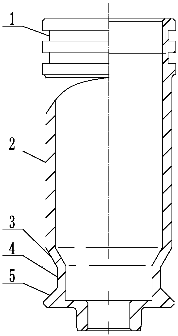
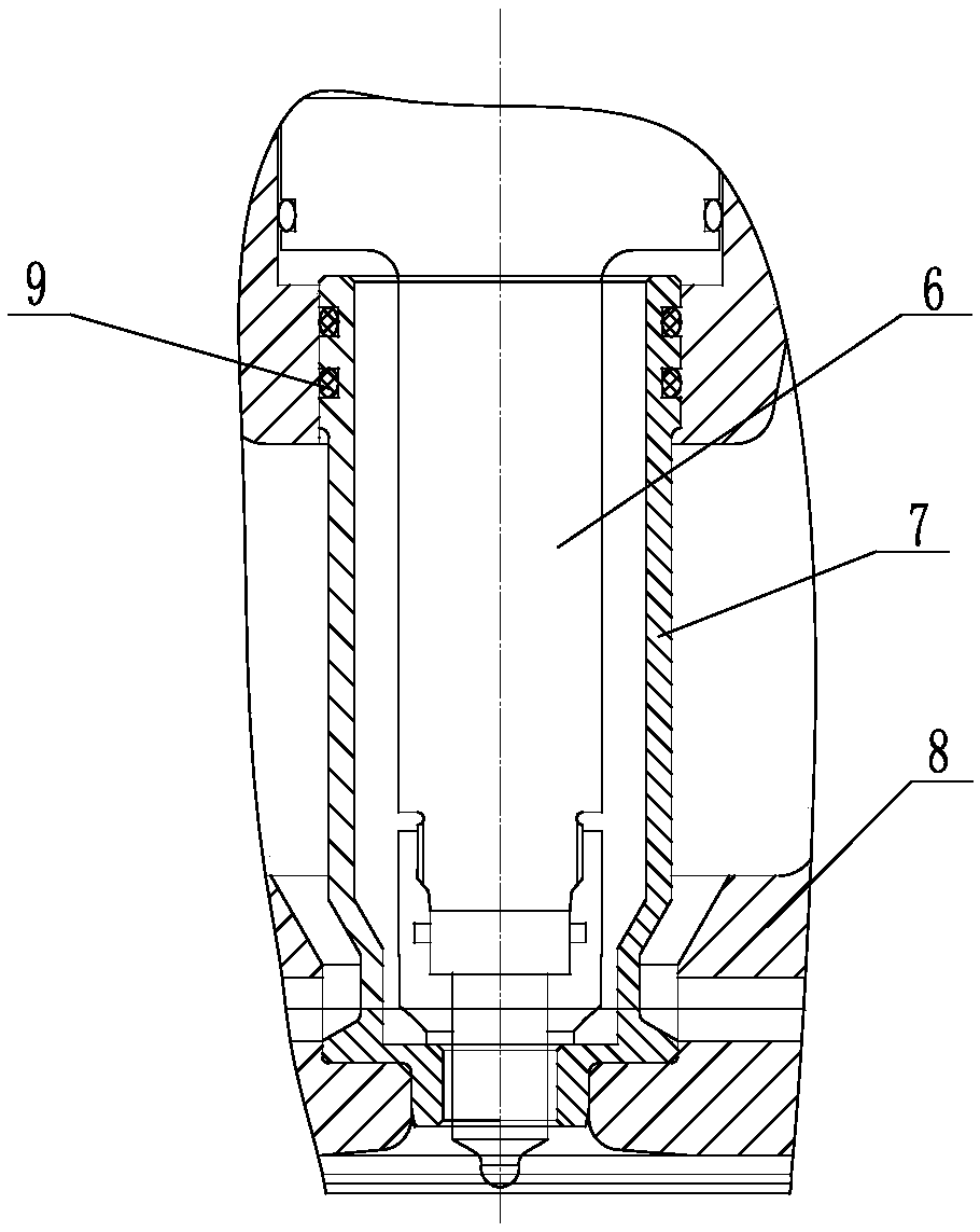
[0018] like Figure 1 ~ Figure 2 As shown, the water seal device of the present invention includes a water seal body 7, and the water seal body 7 includes three sections of cylindrical cavities arranged up and down, which are respectively the first cylindrical cavity body 2 and the second cylindrical cavity body 4 and the third cylindrical cavity body, a cylindrical cavity body 3 with a variable diameter section is arranged between the first cylindrical cavity body 2 and the second cylindrical cavity body 4, an annular sealing groove 1 is arranged on the upper part of the first cylindrical cavity body 2, and the second A tapered boss 5 is arranged between the second cylindrical cavity body and the third cylindrical cavity body. The diameter of the bottom of the tapered boss 5 is larger than the diameter of the top. The water seal body 7 adopts 2cr13 stainless steel. A hi...


PUM


Abstract

The invention is mainly applied to sealing components between an air cylinder cover and an oil sprayer, and particularly relates to a water seal sleeve device. The water seal sleeve device comprises awater seal sleeve body. The water seal sleeve body comprises three cylindrical cavities arranged up and down, and the cylindrical cavities comprise the first cylindrical cavity, the second cylindrical cavity and the third cylindrical cavity. A reducer cylindrical cavity is arranged between the first cylindrical cavity and the second cylindrical cavity. An annular sealing groove is arranged on theupper portion of the first cylindrical cavity. A conic boss is arranged between the second cylindrical cavity and the third cylindrical cavity. According to the water seal sleeve device, the contactarea of the water seal sleeve and an air cylinder sleeve is increased, and impacting of impacts to the position, where water is prone to leaking, of the air cylinder cover is reduced. Through the water seal sleeve device, the problem of water leaking of the air cylinder cover is solved successfully, the service life of the air cylinder cover is prolonged to a great degree, and the reliability of adiesel engine is guaranteed.

Description

technical field [0001] The invention relates to a water seal sleeve device, which is mainly used in parts sealed between a cylinder head and a fuel injector. Background technique [0002] When the diesel engine is working, the working environment inside the cylinder is very harsh. When the fuel burns and explodes, it generates high pressure on the cylinder head, so that the top surface of the combustion chamber at the bottom of the cylinder head bears periodic alternating pressure. First, due to the periodic alternating pressure action, alternating stress will be generated on the lower structure of the cylinder head, and the material will be fatigued and damaged. Second, due to the effect of alternating pressure, the cylinder head produces high-frequency vibration, which makes the local high vacuum, high pressure and high temperature generated in a timely manner between the cooling water and the cooling water adhesion layer on the inner cavity surface of the cooling water of...

Claims


Application Information

Patent Timeline
Patent Type & Authority Applications(China)
IPC IPC(8): F02F11/00
CPCF02F11/002
Inventor 谷萌牛志坚李龙孙镇
Owner ZICHAI POWER CO LTD
Why Eureka
Try Eureka