Anti-disassembly connector, connector assembly and air conditioner
A joint and anti-disassembly technology, which is applied in the direction of couplings, mechanical equipment, etc.
- Summary
- Abstract
- Description
- Claims
- Application Information
AI Technical Summary
Problems solved by technology
Method used
Image
Examples
Embodiment 1
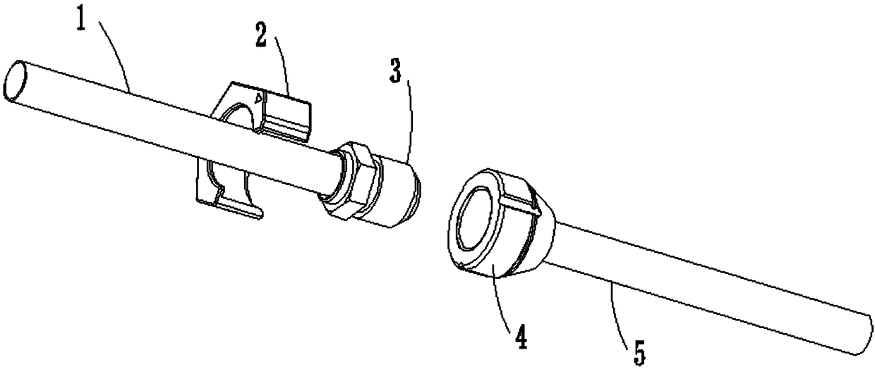
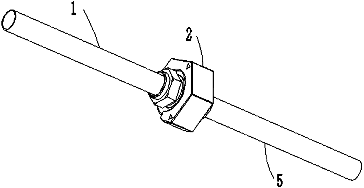
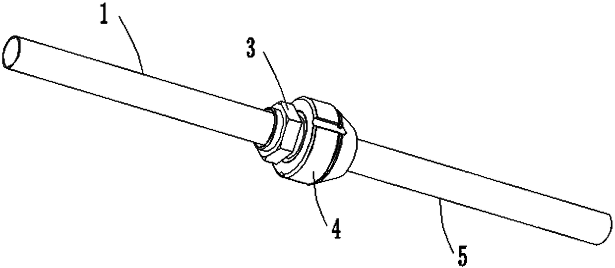
[0042] like Figure 1-9 As shown, a disassembly-resistant connector includes a connector body 4 and auxiliary tooling 2 .
[0043] like Figure 4 As shown, the connector body 4 is provided with a threaded hole 41 and a slot 42; specifically, the connector body 4 is cylindrical, and one end of the connector body 4 is provided with a gradually narrowing bell mouth, thereby connecting with the bell mouth The pipe 5 communicates; wherein, the threaded hole 41 is provided through the axis of the connector, so that the threaded hole 41 can be screwed with the pipe joint 3 to realize assembly; the slot 42 is arranged along the axis of the connector body 4, thereby , the slot 42 is convenient to cooperate with the auxiliary tooling 2 to realize assembly.
[0044] In this embodiment, the outer edge of the connector body 4 does not match the screwing tool such as a wrench. Therefore, the screwing tool such as a wrench cannot be used to rotate the connector body 4 , and the auxiliary t...
Embodiment 2
[0051]Compared with the above-mentioned embodiments, this embodiment differs in that the auxiliary tooling 2 in this embodiment includes a first end face 22, a second end face 23, a third end face 24, a fourth end face 25 and a fifth end face 26; wherein , the first end surface 22, the second end surface 23, the third end surface 24, the fourth end surface 25 and the fifth end surface 26 are sequentially connected to form the engaging cavity 21, specifically, the angle between the five is 120 degrees, thus, it is convenient Cooperate with a tightening tool such as a wrench; the first end surface 22 and the fifth end surface 26 are disconnected to form a notch 212 , thus, under the action of the notch 212 , the assembly and disassembly of the auxiliary tooling 2 and the connector body 4 are realized.
[0052] In this embodiment, the first end face 22 and the fourth end face 25 form a first anti-disassembly structure; when the auxiliary tooling 2 reduces the torque transmission e...
Embodiment 3
[0055] Compared with the above-mentioned embodiments, this embodiment differs in that the engaging cavity 21 in this embodiment is provided with a surrounding edge 213; when the engaging cavity 21 fits on the connector body 4, the surrounding edge 213 abuts against the connecting head body 4. Specifically, one end of the engaging cavity 21 is provided with a surrounding edge 213, and the surrounding edge 213 and the block 211 are perpendicular to each other, thus, under the action of the surrounding edge 213, the position of the auxiliary tooling 2 on the connector body 4 can be positioned. position to prevent the auxiliary tooling 2 from sliding down along the outer edge of the connector body 4 .
PUM
 Abstract
Description
Claims
Application Information
 - R&D
- Intellectual Property
- Life Sciences
- Materials
- Tech Scout
- Unparalleled Data Quality
- Higher Quality Content
- 60% Fewer Hallucinations
Browse by: Latest US Patents, China's latest patents, Technical Efficacy Thesaurus, Application Domain, Technology Topic, Popular Technical Reports.
© 2025 PatSnap. All rights reserved.Legal|Privacy policy|Modern Slavery Act Transparency Statement|Sitemap|About US| Contact US: help@patsnap.com


