Electrical rotating machine

A technology for rotating electrical machines and rotors, applied in electrical components, electromechanical devices, electrical components, etc., can solve problems such as increased number of components, increased cost, and complex structure, and achieve the effect of suppressing the decline of energy transfer efficiency and simple structure

Inactive Publication Date: 2016-03-23
SUZUKI MOTOR CORP
View PDF6 Cites 2 Cited by
  • Summary
  • Abstract
  • Description
  • Claims
  • Application Information

AI Technical Summary

Problems solved by technology

[0007] However, even in such a rotating electrical machine, permanent magnets are used on the rotor side to efficiently rotate in order to achieve a compact structure and high output (high torque). Rare permanent magnets cost more
[0008] In addition, when electromagnets are used instead of permanent magnets to supply power to the electromagnets on the rotor side from the power supply battery, for example, slip rings for supplying power to the coils or inverters are required, which complicates the structure and increases the number of parts. , cost increases

Method used


Image

  • Electrical rotating machine
  • Electrical rotating machine
  • Electrical rotating machine

Examples


Embodiment Construction

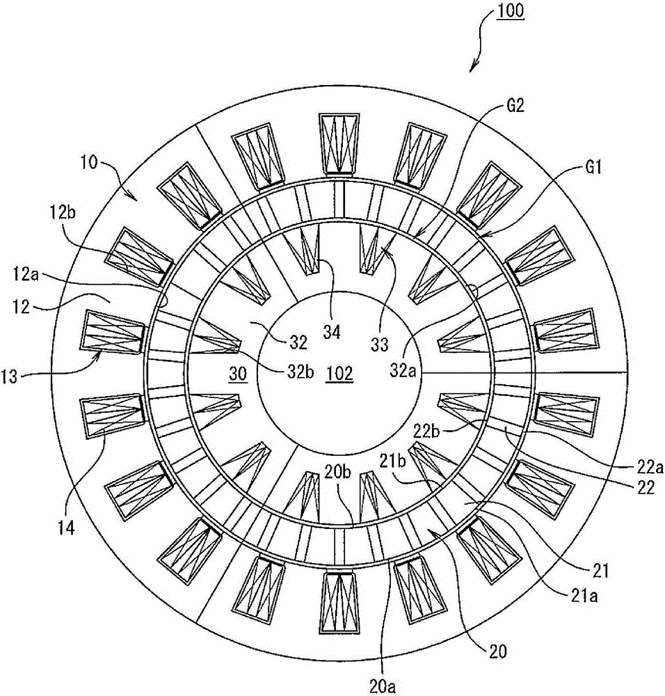
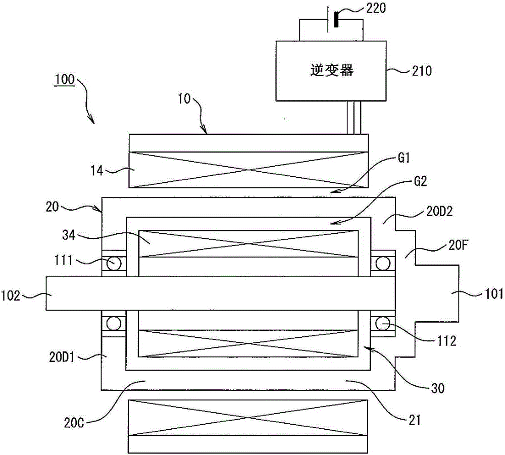
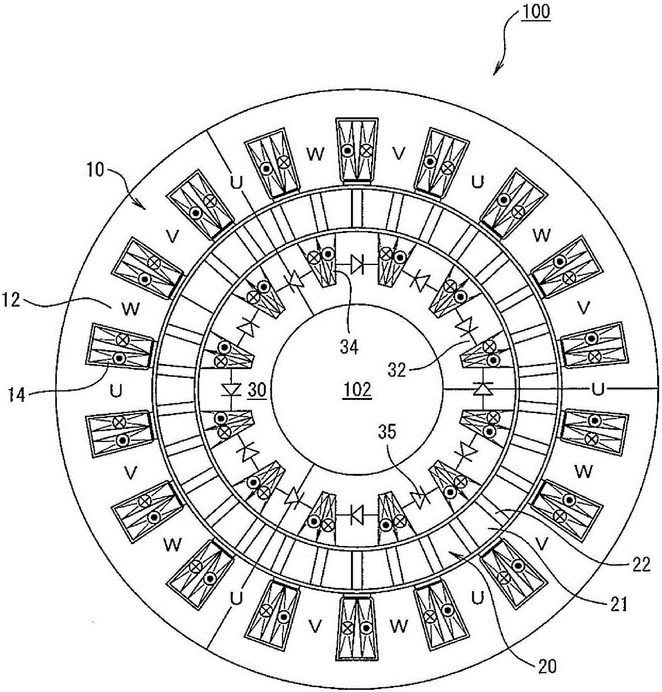
[0047] Embodiments of the present invention will be described in detail below with reference to the drawings. Figure 1 to Figure 6 It is a figure which shows the rotating electric machine which concerns on one Embodiment of this invention.

[0048] exist figure 1 and figure 2 Among them, a rotating electric machine (two-rotor type electric machine) 100 includes: a stator 10 formed in a substantially cylindrical shape; A rotation input shaft (also referred to simply as a rotation shaft) 101; and an inner rotor (first rotor) 30, which is rotatably housed in the outer rotor 20, and a rotation output shaft (also referred to only as axis of rotation) 102 .

[0049] The stator 10 is formed with a plurality of stator teeth 12 extending from the radially outer side toward the radially inner side so that the inner peripheral surface 12 a side faces the outer peripheral surface 20 a of the outer rotor 20 across the air gap G1 . The stator tooth 12 is provided with an armature coi...


PUM


Abstract

Provided is an simple, in construction, and inexpensive electrical rotating machine of the double-rotor type with a limited efficiency drop in energy transmission. The electrical rotating machine (100) comprises: a stator (10) including armature coils (14) capable of generating magnetic flux when energized; an inner rotor (30) driven to rotate when the magnetic flux passes therethough; and an outer rotor (20) driven to rotate in a magnetic path of the magnetic flux that passes through the inner rotor, the outer rotor having portions of different materials, in permeability, which are situated along the periphery of the outer rotor, the inner rotor having a plurality of salient poles situated along the periphery of the inner rotor, the salient poles being wound by induction coils which generate induced current when linked by the magnetic flux generated by the armature coils.

Description

technical field [0001] The present invention relates to a rotating electric machine of the double rotor type. Background technique [0002] A rotating electrical machine is installed in various devices as a power source. For example, in the case of a vehicle, it is mounted alone to function as a power source for an electric vehicle, or is mounted together with an internal combustion engine to function as a power source for a hybrid vehicle. Especially in the case of a hybrid vehicle, high power transmission efficiency is required, and high torque is also required to ensure acceleration performance and step-crossing performance. [0003] For example, as a power transmission path that connects an internal combustion engine, a rotating electric machine, and a driving wheel in series (series type), a so-called range-extending method is sometimes used: the driving wheel is driven to rotate by a rotating electric machine, and the power of the internal combustion engine is converte...

Claims


Application Information

Patent Timeline
Patent Type & Authority Applications(China)
IPC IPC(8): H02K16/02H02K11/00
CPCH02K16/02H02K1/223H02K11/33
Inventor 青山真大
Owner SUZUKI MOTOR CORP
Why Eureka
Try Eureka