
Eureka
For R&D, Eureka makes reading and utilizing patents & technical documents easy.
Eureka AIR
Designed for self-driven R&D workflows. Generate viable solutions, solve complex R&D challenges, empower your innovation with AI.

Eureka Materials
Designed for material experts only. Revolutionize your material R&D, from search, analyze, to developing new materials.

TechResearch
Generate reliable direction feasibility study reports for your R&D in just a few steps.

TechSeek
Discover and master advanced knowledge NOW. Basics, ideas, possibilities, all at once.

TechMind
As an expert in R&D Theories, TechMind can generates customized viable solutions instantly.

TechRisk
Analyze your overall solution with one click, know your potential R&D risks in advance.

TechMonitor
Get weekly tech updates, stay abreast of the latest tech innovations and key insights.
Multifunctional bracket for desktop telecommunication equipment
A telecommunications equipment, multi-functional technology, applied in the direction of machine/stand, mechanical equipment, supporting machine, etc., can solve problems that affect the service life and work stability of desktop telecommunications equipment, abnormal operation of components, and easy vibration, etc., to achieve protection Desktop equipment, reduced space occupation, low cost effect
- Summary
- Abstract
- Description
- Claims
- Application Information
AI Technical Summary
Problems solved by technology
Method used
Image

Examples
Embodiment 1
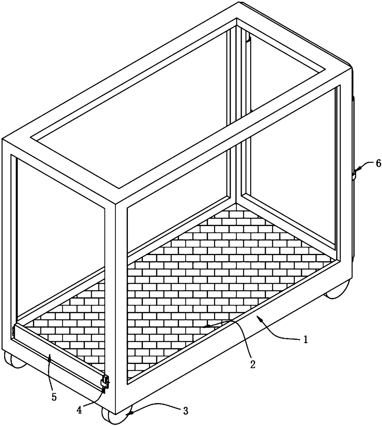
[0038] A multifunctional support for desktop telecommunication equipment, such as figure 1 and Figure 14 As shown, including a rectangular frame 1, a balance plate 2 is provided at the inner bottom of the rectangular frame 1, and the four corners of the inner bottom and top of the rectangular frame 1 are all glued with cushions 8, and the four corners of the lower surface of the rectangular frame 1 are all Casters 3 are installed.
[0039] Further, the cushion 8 is made of rubber material, which can protect the top of the desktop device because of its good elasticity.
[0040] It is worth noting that the caster 3 involved in this embodiment adopts the universal caster of model 1817 produced by Foshan Junyuewei Hardware Plastic Products Co., Ltd., and its supporting mounting screws can also be provided by the manufacturer. In addition, this The locking components and modules involved in the invention are all prior art, which can be realized by those skilled in the art. Needl...
Embodiment 2
[0045] As the second embodiment of the present invention, in order to facilitate the movement of the rectangular frame 1, the inventors made improvements to one side of the rectangular frame 1, as a preferred embodiment, such as Figure 4~7 As shown, the rear side of the rectangular frame 1 is provided with a pull rod device 6, the pull rod device 6 includes a U-shaped pull rod 60 and sleeves 62 sleeved at both ends of the U-shaped pull rod 60, and the center of the sleeve 62 is sleeved with a rectangular The frame 1 is welded with an arc buckle 61 , and the bottom end of the sleeve 62 is provided with a second hinge 63 , and the sleeve 62 is hinged to the rectangular frame 1 through the second hinge 63 .
[0046] Further, a number of anti-slip blocks 601 are equidistantly arranged on the inner side of the U-shaped tie rod 60. The two side walls of the U-shaped tie rod 60 near the end are symmetrically provided with limiting holes 602. The limiting holes 602 are embedded with l...
Embodiment 3
[0050] As a third embodiment of the present invention, in order to protect the desktop equipment in the rectangular frame 1, the inventors made improvements to the inside of the rectangular frame 1, as a preferred embodiment, such as Figures 8 to 13 As shown, the four corners of the lower surface of the balance board 2 are provided with shock absorbers 7, and the shock absorbers 7 include intersecting first movable rods 70 and second movable rods 71, the first movable rods 70 and the second movable rods 71 The center is provided with a second rotating shaft groove 701, the second rotating shaft groove 701 is embedded with a second rotating shaft 72, the first movable rod 70 and the second movable rod 71 are provided with an elastic cord 73 near the bottom end, and the first movable rod One end of the first movable rod 70 and the second movable rod 71 is provided with a third hinge 74 , and the other end of the first movable rod 70 and the second movable rod 71 is provided with...
PUM
 Abstract
Description
Claims
Application Information
 - R&D Engineer
- R&D Manager
- IP Professional
- Industry Leading Data Capabilities
- Powerful AI technology
- Patent DNA Extraction
Browse by: Latest US Patents, China's latest patents, Technical Efficacy Thesaurus, Application Domain, Technology Topic, Popular Technical Reports.
© 2024 PatSnap. All rights reserved.Legal|Privacy policy|Modern Slavery Act Transparency Statement|Sitemap|About US| Contact US: help@patsnap.com