Cooling treatment equipment for machining

A processing equipment and mechanical processing technology, applied in metal processing equipment, lighting and heating equipment, metal processing machinery parts, etc., can solve the problems of cumbersome operation, affecting the heating effect, high processing temperature, etc., to avoid shaking, convenient operation, Ease of processing

Inactive Publication Date: 2019-01-01
熊飞燕
View PDF0 Cites 2 Cited by
  • Summary
  • Abstract
  • Description
  • Claims
  • Application Information

AI Technical Summary

Problems solved by technology

[0005] Aiming at the deficiencies of the prior art, the present invention provides a cooling processing equipment for mechanical processing, which solves the problem that a lot of heat will be generated during processing. Since the generated heat cannot b...

Method used


Image

  • Cooling treatment equipment for machining
  • Cooling treatment equipment for machining
  • Cooling treatment equipment for machining

Examples


Embodiment approach 1

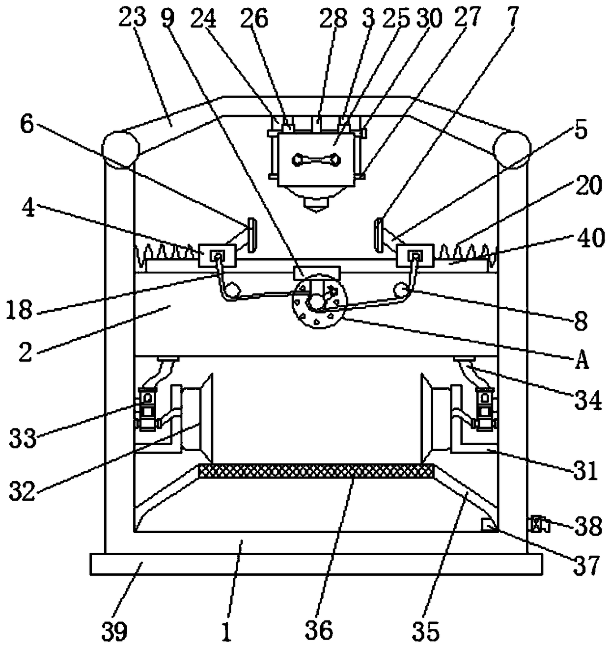
[0032] Implementation method 1, please refer to Figure 1-8, a mechanically processed cooling treatment device, comprising a housing 1, the top of the housing 1 is fixedly connected with a case cover 23, the bottom of the case cover 23 is fixedly connected with a connecting plate 24, and the front of the connecting plate 24 is fixedly connected with a limiting plate 28, sliding The inner surfaces of the block 26 and the limiting plate 28 are all provided with limiting holes 29, the inner surfaces of the limiting holes 29 are movably connected with the limiting rods 30, and the left and right sides of the connecting plate 24 fronts are all fixedly connected with the second slide rail 3, Utilize the cooperation between the second slide rail 3 and the sliding block 26 to make the processing device 25 slide up and down on the second slide rail 3, and then adjust the position of the processing device 25, and then utilize the gap between the stop bar 30 and the stop hole 29 to The c...

Embodiment approach 2

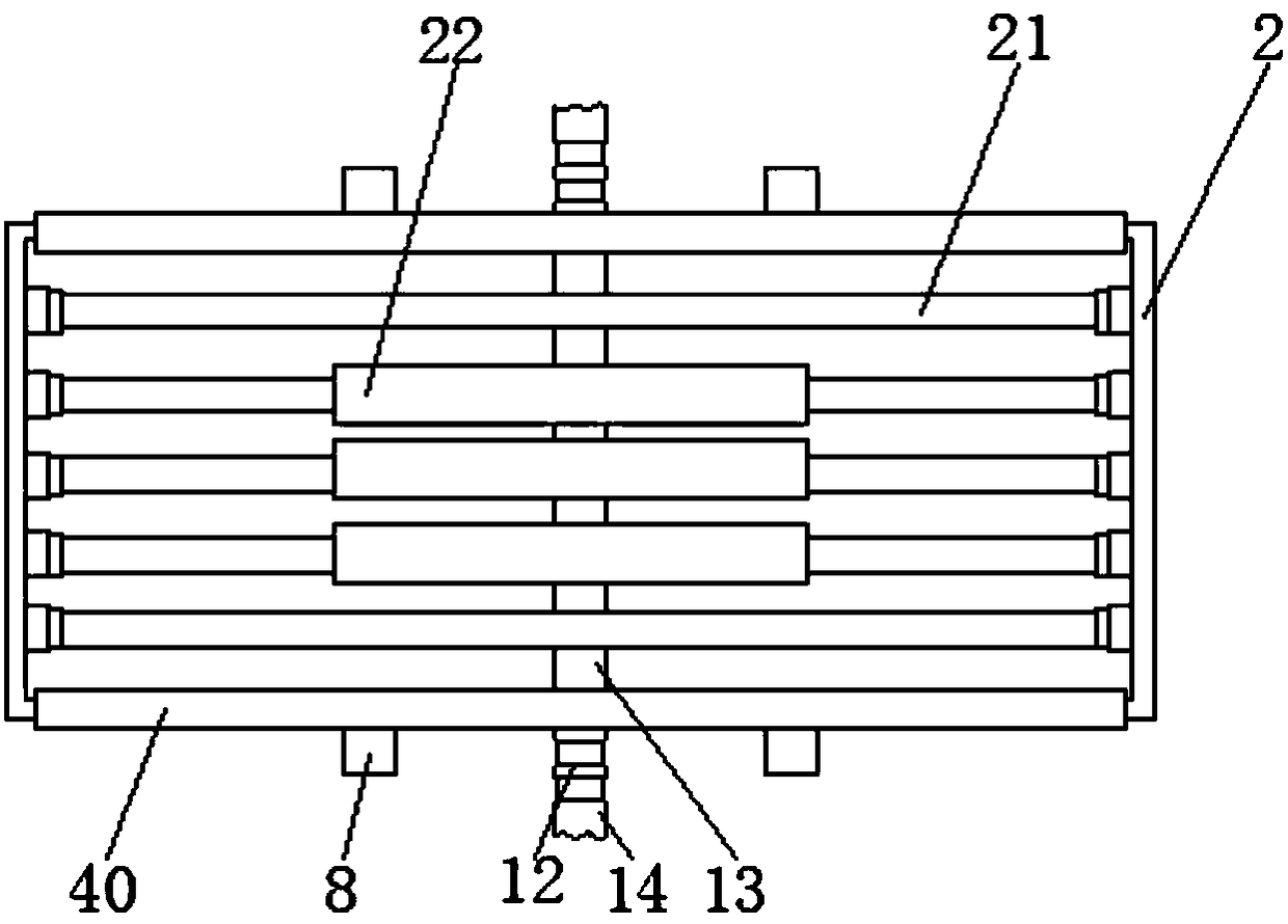
[0033] Implementation mode two, please refer to Figure 1-8 , a mechanically processed cooling treatment device, comprising a casing (1), characterized in that: the inside of the casing (1) is fixedly connected with a cooling box (2), and the front and rear sides of the cooling box (2) are fixed The first slide rails (40) are connected, the two first slide rails (40) are slidably connected with slide plates (4), and the opposite sides of the two slide plates (4) are fixedly connected with support plates (5), and the side of the support plate (5) away from the sliding plate (4) is fixedly connected with a clamping plate (6), and one side of the clamping plate (6) is fixedly connected with a buffer plate (7), and the cooling box ( 2) The front and rear sides are rotatably connected with guide posts (8), the front and rear sides of the cooling box (2) are fixedly connected with fixed blocks (9), and the bottom of the fixed block (9) is fixedly connected with connecting Rod (10),...

Embodiment approach 3

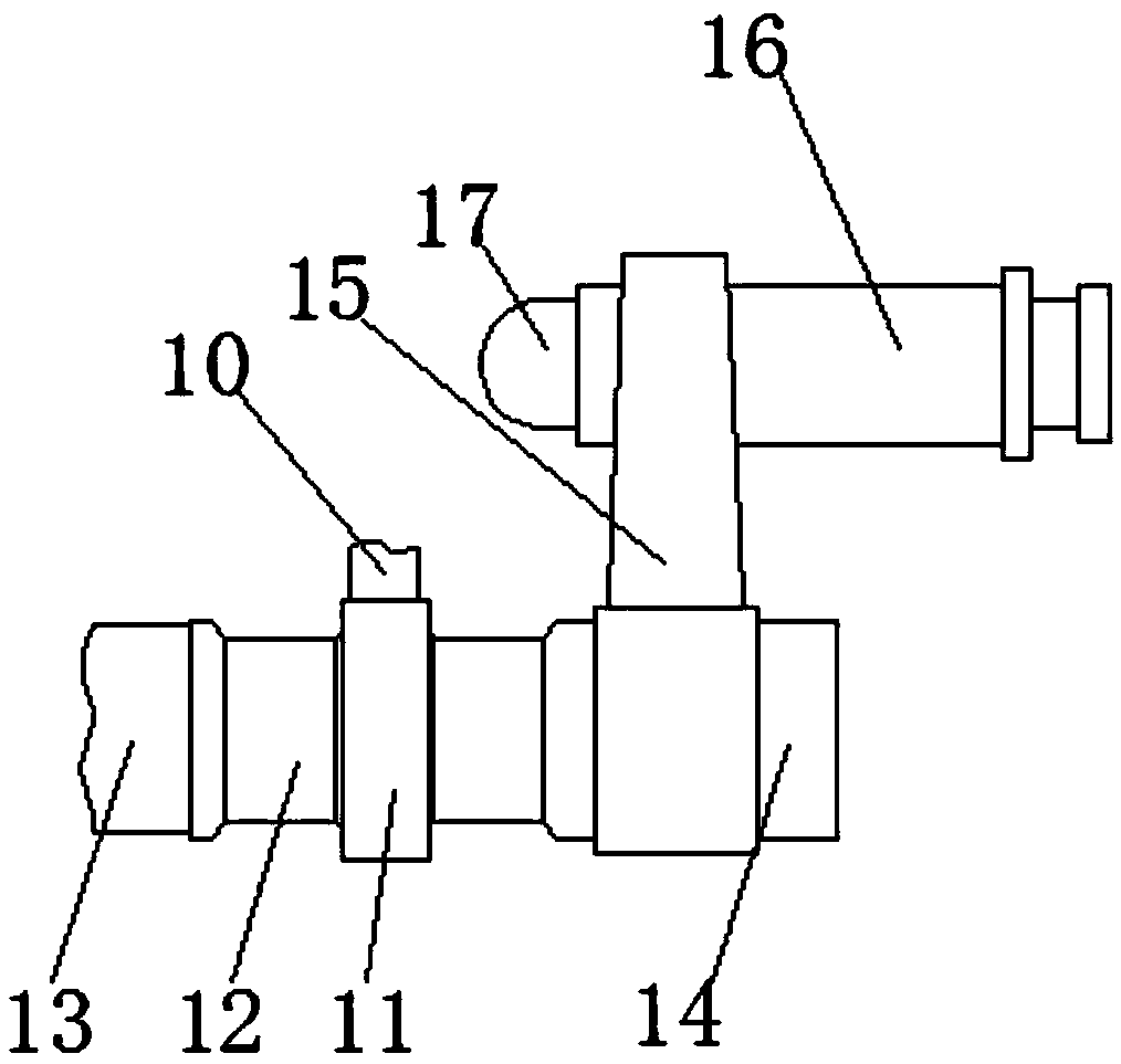
[0034] Implementation Mode 3, please refer to Figure 1-8 , a mechanically processed cooling treatment device, one end of the outer surface of the winding post (12) is fixedly connected with a rotating rod (14), and the outer surface of the rotating rod (14) is fixedly connected with a rocker (15), A handle (16) is fixedly connected to the inner surface of the rocker (15), and the inner surface of the handle (16) is slidably connected to a limiting column (17).


PUM


Abstract

The invention discloses cooling treatment equipment for machining. The cooling treatment equipment comprises a housing, wherein a cooling box is fixedly connected to the interior of the housing, firstsliding rails are fixedly connected to the front and back sides of the cooling box, sliding plates are connected to the outer surfaces of the two first sliding rails in a sliding mode, support platesare fixedly connected to the opposite sides of the two sliding plates, clamping plates are fixedly connected to one side, which is far from the sliding plates, of the support plates, and buffer plates are fixedly connected to one side of the clamping plates. The cooling treatment equipment relates to the technical field of machinery. According to the processing device for machinery, heat generated by processing can be absorbed by utilizing the cooling box when the processing device is used for processing, so that the processing effect cannot be influenced by the overhigh processing environment; additionally, the sliding plates can be driven to move on the first sliding rails by utilizing the matching between a wrapping post and a pull rope, so that the clamping plates are driven to clampa to-be-processed mechanical tool, the mechanical tool is convenient to process by the processing device, the to-be-processed mechanical tool is prevented from deflecting, and the processing is accurate.

Description

technical field [0001] The invention relates to the technical field of machinery, in particular to cooling treatment equipment for mechanical processing. Background technique [0002] Machinery refers to the general term of machines and mechanisms. Machinery is a tool device that can help people reduce the difficulty of work or save labor. Items such as chopsticks, brooms, and tweezers can all be called machines. They are simple machines. A complex machine is composed of two or more simple machines. These more complex machines are usually called machines. From the point of view of structure and motion, there is no difference between a mechanism and a machine, and it is generally called a machine. Mechanical engineering is based on the relevant natural science and technical science as the theoretical basis, combined with the technical experience accumulated in production practice, to study and solve the theoretical and practical problems in the development, design, manufact...

Claims


Application Information

Patent Timeline
IPC IPC(8): F25D1/02B23Q3/06
CPCF25D1/02B23Q3/06
Inventor 不公告发明人
Owner 熊飞燕
Why Eureka
Try Eureka