Packaging structure
A technology of packaging structure and packaging cover, which is applied to electrical components, electrical solid devices, circuits, etc., can solve the problems of reduced alignment accuracy and offset of the falling position of the substrate, and achieves the effect of ensuring alignment accuracy.
- Summary
- Abstract
- Description
- Claims
- Application Information
AI Technical Summary
Problems solved by technology
Method used
Image

Examples
Embodiment Construction
[0027] In order to make the purpose, technical solutions and advantages of the embodiments of the present invention more clear, the following will clearly and completely describe the technical solutions of the embodiments of the present invention in conjunction with the drawings of the embodiments of the present invention. Apparently, the described embodiments are some, not all, embodiments of the present invention. All other embodiments obtained by those skilled in the art based on the described embodiments of the present invention belong to the protection scope of the present invention.
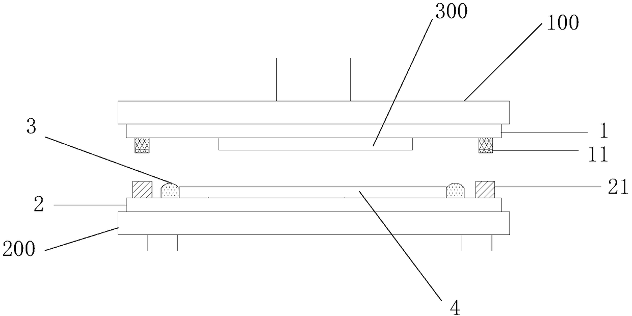
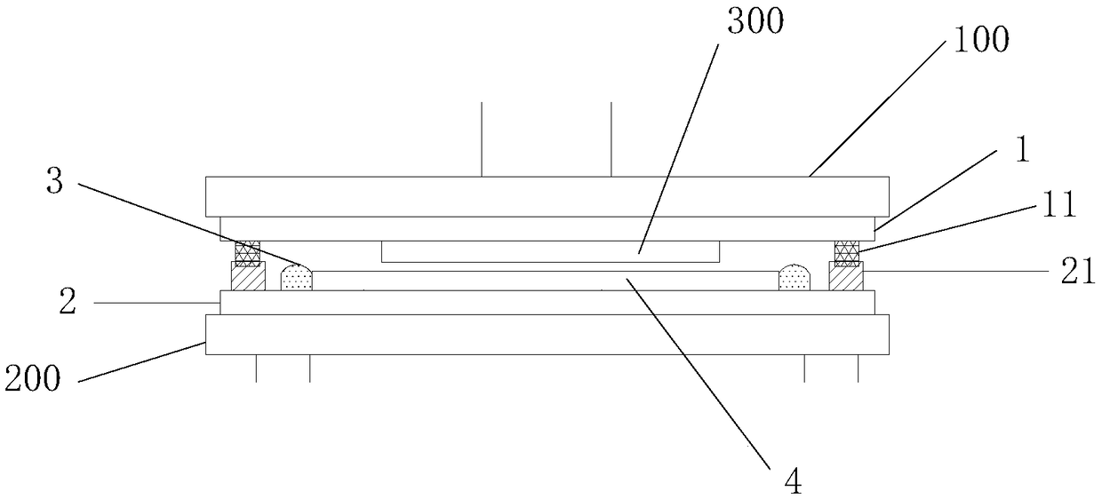
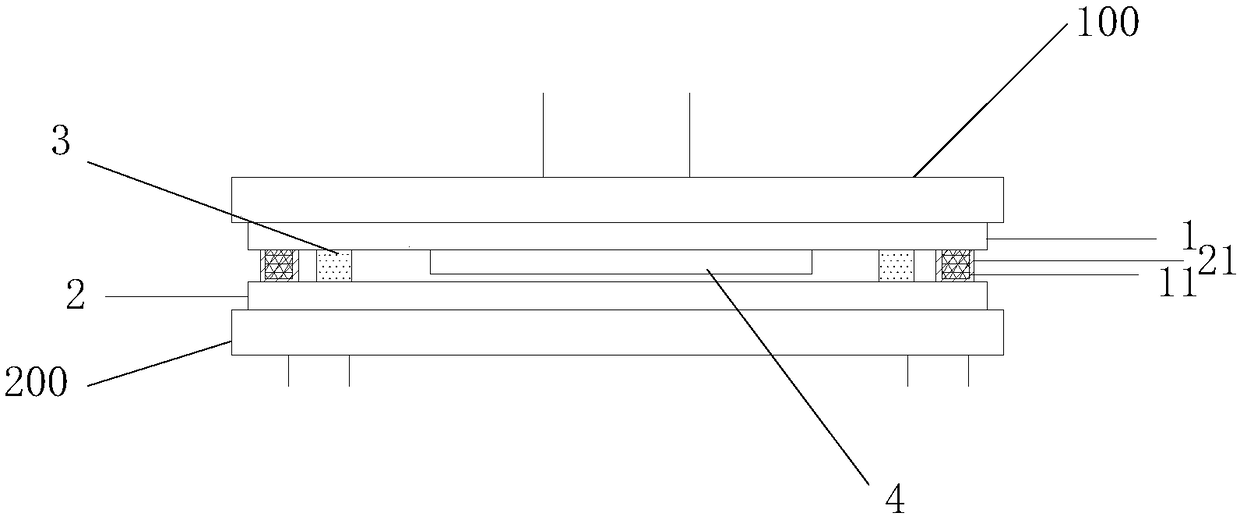
[0028] During the release process of the substrate 1, due to the vibration of the machine and the turbulence of the residual gas in the chamber, the falling position of the substrate 1 is shifted, which reduces the alignment accuracy. To solve the above problems, this embodiment provides a packaging structure, including the substrate 1 and the package cover 2, the substrate 1 is provided wi...
PUM
 Abstract
Description
Claims
Application Information