
Current balanced flat copper wire wave winding armature winding

An armature winding and current balance technology, applied in the shape/style/structure of the winding conductor, etc., can solve the problems of increased winding temperature, unbalanced current of the three branches, and damage to the motor insulation system due to the inner temperature, so as to improve the overall performance, the effect of improving electrical performance indicators

Pending Publication Date: 2019-01-01
华域汽车电动系统有限公司
View PDF6 Cites 9 Cited by
  • Summary
  • Abstract
  • Description
  • Claims
  • Application Information

AI Technical Summary

Problems solved by technology

[0002] For the flat copper wire wave winding armature winding in the prior art, when the number of conductors per slot is N=6 layers, the connection mode of the three-phase winding is often selected: 1, 2 layers form a branch circuit (inner layer), 3, The 4th layer constitutes a branch (middle layer), the 5th and 6th layers are another branch (outer layer), and the three branches are connected in parallel, so that the three branches are affected by the skin effect and proximity effect of the winding when the motor load is running. , it is easy to cause the current unbalance of the three branches (the higher the frequency of the motor power supply, the greater the unbalance), resulting in the uneven temperature distribution of the three branches, and the problem that the temperature of the outer, middle and inner layer windings gradually increases
Ultimately, the inner layer temperature is too high and damages the insulation system of the motor

Method used


Image

  • Current balanced flat copper wire wave winding armature winding
  • Current balanced flat copper wire wave winding armature winding
  • Current balanced flat copper wire wave winding armature winding

Examples


specific Embodiment approach

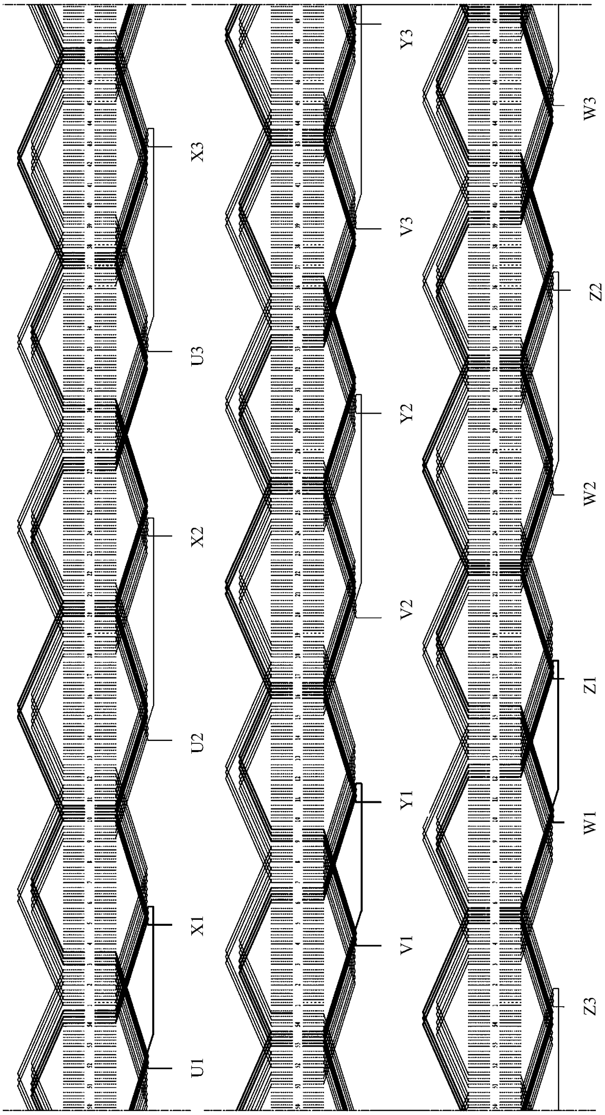
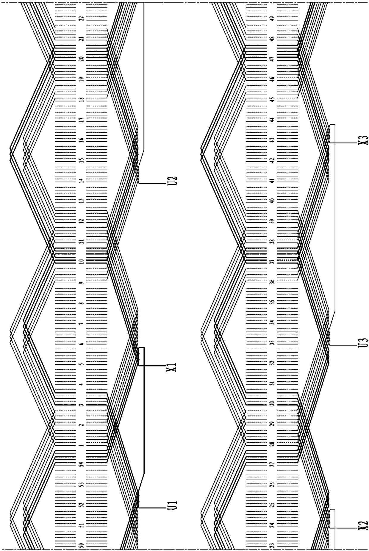
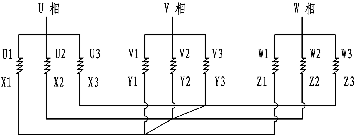
[0019] The flat copper wire wave winding armature winding of the present invention is a six-layer wave winding structure, and the winding lead-out terminals U1, U2, U3, V1, V2, V3, W1, W2, W3, X1, X2, X3, Y1 , Y2, Y3, Z1, Z2, and Z3 subscript numbers 1, 2, and 3 correspond to star point branch 1, star point branch 2, and star point branch 3 respectively.

[0020] This flat copper wire wave winding does not adopt prior art scheme (1, 2 layers constitute a branch (inner layer), 3, 4 layers are a branch (middle layer), 5, 6 layers are another branch (outer layer) Layer), three branches connected in parallel), each phase winding also has three branches, but each branch is composed of 1, 2, 3, 4, 5, 6 layers of flat copper wires.

[0021] This measure is applicable to the number of conductor layers per slot N=6, and the parallel branch is 3, all kinds of stator slot numbers (including 36, 48, 54, 60, 72, 84, 90 slots, etc.) are applicable, and the winding pitch is Suitable for sho...


PUM


Abstract

The invention provides a current balanced flat copper wire wave winding armature winding comprising a U-phase winding, a V-phase winding and a W-phase winding. The three parallel branches of the U-phase winding enter from the first layer of the same corresponding slot of each pair of poles and exit from the first layer of the same corresponding slot of each pair of poles. The three parallel branches of the V-phase winding enter from the first layer of the same corresponding slot of each pair of poles and exit from the first layer of the same corresponding slot of each pair of poles. The threeparallel branches of the W-phase winding enter from the first layer of the same corresponding slot of each pair of poles and exit from the first layer of the same corresponding slot of each pair of poles. According to the current balanced flat copper wire wave winding armature winding, the temperature non-uniformity of the outer, intermediate and inner windings during load operation of the motor is improved when the three branches are connected in parallel, and the electric performance index of the motor is improved. The biggest characteristic is that the current of the three parallel branchesis completely balanced and there is no current amplitude and phase difference among the three branches during load operation of the motor so as to improve the overall performance of the motor.

Description

technical field [0001] The invention relates to the field of motors, in particular to a flat copper wire wave winding armature winding, in particular to a current balanced flat copper wire wave winding armature winding. Background technique [0002] For the flat copper wire wave winding armature winding in the prior art, when the number of conductors per slot is N=6 layers, the connection mode of the three-phase winding is often selected: 1, 2 layers form a branch circuit (inner layer), 3, The 4th layer constitutes a branch (middle layer), the 5th and 6th layers are another branch (outer layer), and the three branches are connected in parallel, so that the three branches are affected by the skin effect and proximity effect of the winding when the motor load is running. , It is easy to cause the current imbalance of the three branches (the higher the frequency of the motor power supply, the greater the unbalance), resulting in uneven temperature distribution of the three bran...

Claims


Application Information

Patent Timeline
Patent Type & Authority Applications(China)
IPC IPC(8): H02K3/16
CPCH02K3/16
Inventor 姜华宋志环曹红飞赵航张亚徐锋
Owner 华域汽车电动系统有限公司
Learn More