
Microwave radiation heating antenna module

An antenna assembly and microwave radiation technology, applied in microwave heating and other directions, can solve problems such as reducing equipment reliability and service life, increasing equipment operating costs, and failing to meet requirements, to improve temperature unevenness, increase service life, Assembly of simple effects

Inactive Publication Date: 2019-08-09
NO 12 RES INST OF CETC
View PDF6 Cites 1 Cited by
  • Summary
  • Abstract
  • Description
  • Claims
  • Application Information

AI Technical Summary

Problems solved by technology

[0004] In order to meet the needs of microwave energy engineering applications, the currently used microwaves at frequencies of 915MHz or 2450MHz cannot penetrate 1m 3 Or a larger volume of medium, so the traditional waveguide feeding method can no longer meet the requirements
However, adding an electric stirring device will significantly reduce the reliability and service life of the equipment, and increase the operating cost of the equipment

Method used


Image

  • Microwave radiation heating antenna module
  • Microwave radiation heating antenna module
  • Microwave radiation heating antenna module

Examples


Embodiment Construction

[0022] In order to illustrate the present invention more clearly, the present invention will be further described below in conjunction with preferred embodiments and accompanying drawings. Similar parts in the figures are denoted by the same reference numerals. Those skilled in the art should understand that the content specifically described below is illustrative rather than restrictive, and should not limit the protection scope of the present invention.

[0023] In the description of the invention, it should be noted that the orientation or positional relationship indicated by the terms "upper", "lower", etc. is based on the orientation or positional relationship shown in the drawings, and is only for the convenience of describing the present invention and simplifying the description, and It is not to indicate or imply that the device or element referred to must have a particular orientation, be constructed in a particular orientation, or operate in a particular orientation,...


PUM


Abstract

The invention discloses a microwave radiation heating antenna module, and relates to the technical field of microwave energy application devices. The antenna module includes a cylindrical outer conductor provided with an opening at one end, and the inner conductor positioned in the outer conductor and supported and fixed with the outer conductor through a support; in the axial direction of the outer conductor, the outer conductor includes a spiral groove penetrating the surface of the outer side of the internal portion of the side wall, the spiral groove comprises at least one screw pitch transition section, and the antenna module can uniformly radiate the electromagnetic waves outwards through the at least one screw pitch transition section of the spiral groove to achieve the uniform heating of the medium.

Description

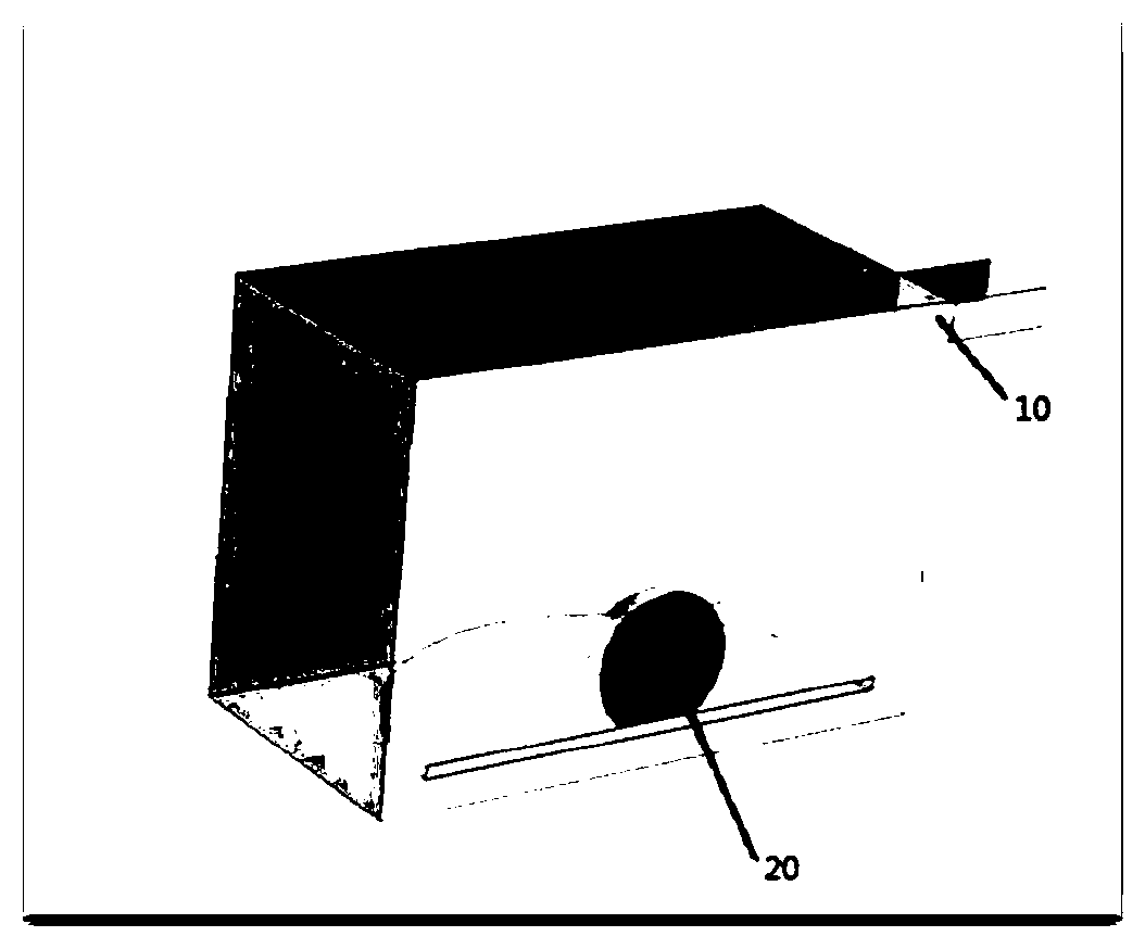
technical field [0001] The invention relates to the technical field of microwave energy application devices. More particularly, it relates to a microwave radiation heating antenna assembly. Background technique [0002] In the prior art, the microwave feeding methods used in the application field of microwave energy are mostly one or more microwave feeding ports 10 for radiation. At present, it is mainly to place solid objects such as food 20 or materials inside the resonant cavity or waveguide, and use the heating effect of microwaves to process the objects. The specific structure is as follows: figure 1 shown. In the cavity, the medium is heated unevenly due to the uneven distribution of the microwave field. [0003] Usually, in order to overcome the problem of inhomogeneity of microwave field distribution, methods such as adding mode stirrer and rotating medium are used inside the microwave cavity to make the medium move relative to the microwave electromagnetic field....

Claims


Application Information

Patent Timeline
Patent Type & Authority Applications(China)
IPC IPC(8): H05B6/72
CPCH05B6/72
Inventor 李瑶杨明华王辉周明干
Owner NO 12 RES INST OF CETC
Learn More