Compound jet pump based on combination of center jet flow and annular jet flow

A technology of annular jet and center jet, which is applied in jet pumps, pumps, non-volume pumps, etc., can solve the problems of poor performance and low efficiency of jet pumps, and achieve improved efficiency, easy processing, and increased action area. Effect

Inactive Publication Date: 2018-06-26
SICHUAN UNIV
View PDF12 Cites 9 Cited by
  • Summary
  • Abstract
  • Description
  • Claims
  • Application Information

AI Technical Summary

Problems solved by technology

[0006] The purpose of the present invention is just to overcome existing defects and deficiencies in the prior art, and to provide a compound jet pump based on the combination of center jet and annular jet. Combined, the nozzle control valve is installed on the working water pipe, thus solving the problems of low efficiency of jet pumps with single center jet and single annular jet, and poor performance after changing working conditions.

Method used


Image

  • Compound jet pump based on combination of center jet flow and annular jet flow
  • Compound jet pump based on combination of center jet flow and annular jet flow
  • Compound jet pump based on combination of center jet flow and annular jet flow

Examples


Embodiment

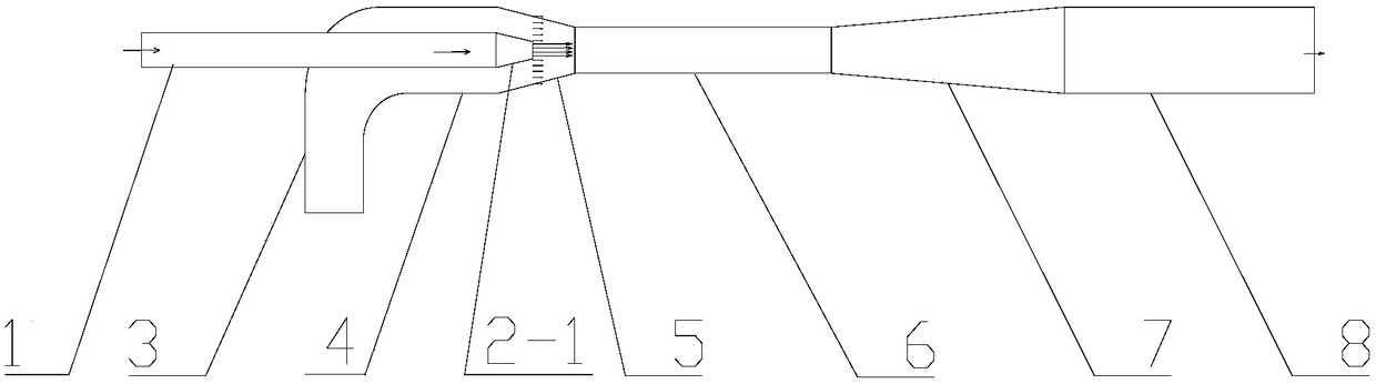
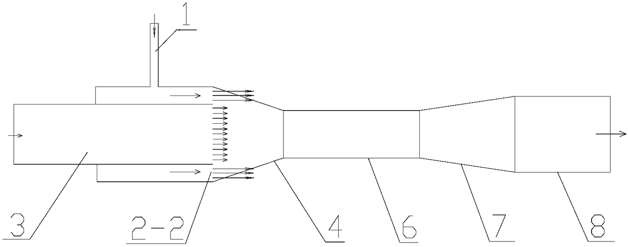
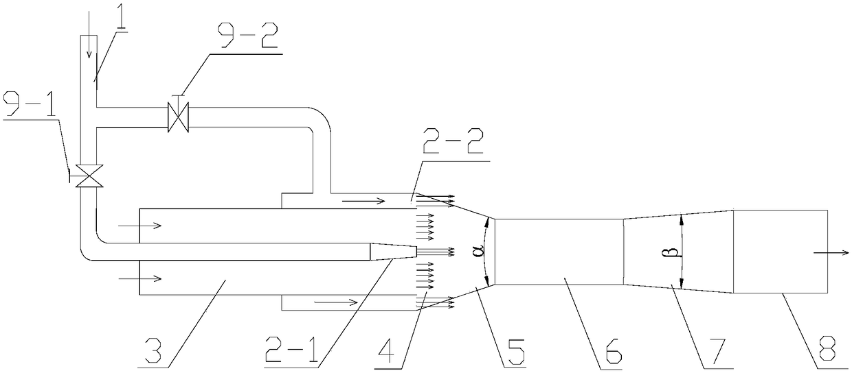
[0023] When the present embodiment adopts the composite jet pump based on the combination of central jet and annular jet to work, the center area ratio of the composite jet pump, that is, the ratio of the area of ​​the throat 6 to the outlet area of ​​the central nozzle 2-1 is 25, so The annular area ratio of the composite jet pump is that the ratio of the area of ​​the throat 6 to the outlet area of ​​the annular nozzle 2-2 is 3.05, and the area ratio of the composite jet pump is the area of ​​the throat 6 to the outlet of the central nozzle 2-1 and the area of ​​the annular nozzle 2-2. 2 The ratio of the sum of the outlet areas is 2.72; the length-to-diameter ratio of the throat pipe 6, that is, the ratio of the length of the throat pipe 6 to the diameter of the throat pipe 6 is 2.5; 20°; the throat 6 is in the form of a cylindrical throat; the diffuser 7 is in the form of uniform diffusion, and its diffusion angle β=6°.

[0024] The working process of the compound jet pump ...


PUM


Abstract

The invention relates to a compound jet pump based on the combination of center jet flow and annular jet flow. The compound jet pump comprises a working water pipe, a center nozzle, an annular nozzle,a water suction tube, a suction-in chamber, a throat tube inlet section, a throat tube, a diffusing tube and a water outlet tube. The compound jet pump further comprises a center nozzle control valveand an annular nozzle control valve. The center nozzle is arranged at the center of the annular nozzle. The center jet flow and the annular jet flow are combined. The compound jet pump solves the problems that a single center jet pump or single annular jet pump is low in efficiency, and the properties can be turned to be poor after working condition change. Compared with a traditional center jetpump and annular jet pump which are mostly used at present, the compound jet pump is small in structural change, the required parts are not greatly increased and technological processing can be achieved easily. The working efficiency is high, the problems which cannot be achieved by the traditional single jet pump are solved, and thus the application prospects are broad.

Description

technical field [0001] The invention relates to a jet pump technology, in particular to a composite novel jet pump based on the combination of a central jet and an annular jet, and belongs to the technical field of fluid machinery. Background technique [0002] Jet pump is a kind of fluid conveying machinery and mixing reaction equipment that utilizes jet shear and turbulent diffusion to transfer mass and energy. The jet pump itself has no moving parts, and has a series of unique advantages such as simple structure, easy processing, convenient maintenance, good sealing, reliable operation, and convenient comprehensive utilization. Jet pumps are widely used in power, machinery and other fields of the national economy, especially suitable for underwater, radiation, corrosion and other occasions, and can produce huge economic and social benefits. [0003] According to the position of the jet pump nozzle and the suction chamber, the jet pump can be divided into two types: centr...

Claims


Application Information

Patent Timeline
Patent Type & Authority Applications(China)
IPC IPC(8): F04F5/10F04F5/46F04F5/48F04F5/54
CPCF04F5/10F04F5/466F04F5/48F04F5/54
Inventor 陈云良赵阳王波徐永
Owner SICHUAN UNIV
Why Eureka
Try Eureka