Multi-spindle tool replacement system and method

A tool replacement and multi-spindle technology, applied in the direction of manufacturing tools, clamping, support, etc., can solve problems such as inability to do one-to-many, customer efficiency discounts, work-related accidents, etc.

Pending Publication Date: 2019-01-04
新代科技(苏州)有限公司
View PDF5 Cites 0 Cited by
  • Summary
  • Abstract
  • Description
  • Claims
  • Application Information

AI Technical Summary

Problems solved by technology

[0002] Existing processing machine tools, such as CNC milling machine tool change systems can be divided into arm type, clamp arm type, bucket hat type, row tool type, etc. according to the type of tool magazine. There are different kinds of tool change systems, but these tool change systems are all for a single spindle, that is to say, the spindle is in a one-to-one situation when changing tools, and it is impossible to achieve a one-to-many situation.
Generally, in the case of multiple spindles with more than 2 spindles, there is basically no CNC milling machine with a tool change system. In the absence of a tool change system, it takes a lot

Method used


Image

  • Multi-spindle tool replacement system and method
  • Multi-spindle tool replacement system and method
  • Multi-spindle tool replacement system and method

Examples


Embodiment Construction

[0056] The following will clearly and completely describe the technical solutions in the embodiments of the present invention with reference to the accompanying drawings in the embodiments of the present invention. Obviously, the described embodiments are only some, not all, embodiments of the present invention. The components of the embodiments of the invention generally described and illustrated in the figures herein may be arranged and designed in a variety of different configurations. Accordingly, the following detailed description of the embodiments of the invention provided in the accompanying drawings is not intended to limit the scope of the claimed invention, but merely represents selected embodiments of the invention. Based on the embodiments of the present invention, all other embodiments obtained by those skilled in the art without making creative efforts belong to the protection scope of the present invention.

[0057] It should be noted that like numerals and let...


PUM


Abstract

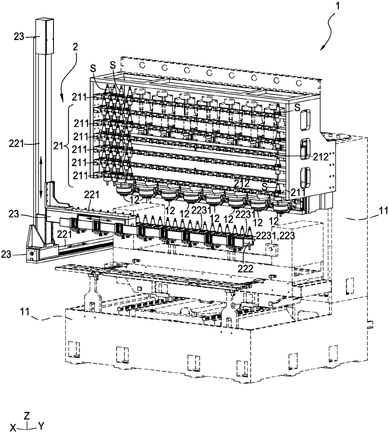
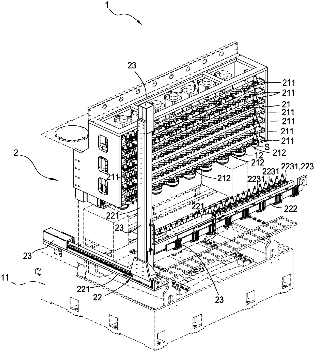
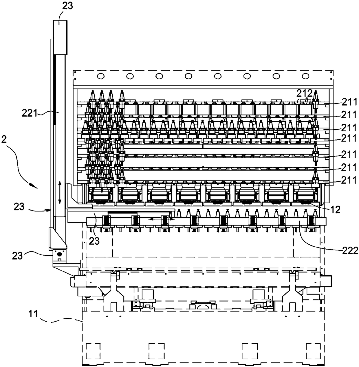
The invention relates to a multi-spindle tool replacement system and method. The system is arranged on a multi-spindle machining tool, the multi-spindle machining tool comprises a machine table, and multiple spindles arranged on the machine table, the spindles can be moved to the tool replacing position of a replacement tool, and the multi-spindle tool replacement system comprises a fixed tool rest and a first moving tool rest; the fixed tool rest is provided with multiple rows of rest bodies, and each rest body is provided with multiple tool rest bases allowing tools to be clamped, the firstmoving tool rest comprises a moving mechanism with moving capacity in the three-dimensional space direction and a rod body arranged on the moving mechanism, the rod body is provided with at least onetaking and putting unit, through moving of the rod body, the taking and putting units are linked, and the taking and putting units take or put back the tool arranged on the fixed tool rest. The movingpath of the taking and putting units comprises the corresponding position of all rest bodies of the fixed tool rest, a tool replacement waiting position close to a tool changing position of the multi-spindle machining tool and the tool changing position of the multi-spindle machining tool. The multi-spindle machining occasion can be subjected to tool changing, and personal operation is reduced.

Description

technical field [0001] The invention relates to a multi-spindle tool changing system and a method thereof. Background technique [0002] Existing processing machine tools, such as CNC milling machine tool change systems can be divided into arm type, clamp arm type, bucket hat type, row tool type, etc. according to the type of tool magazine. There are various tool change systems, but these tool change systems are all for a single spindle, that is to say, the spindle is in a one-to-one situation when changing tools, and it is impossible to achieve a one-to-many situation. Generally, in the case of multiple spindles with more than 2 spindles, there is basically no CNC milling machine with a tool change system. In the absence of a tool change system, it takes a lot of manpower to change the tool during processing. To replace each knife, it is more likely to be dangerous in operation when manually changing the knife, resulting in personal injury and work-related accidents. [0...

Claims


Application Information

Patent Timeline
IPC IPC(8): B23Q3/157
CPCB23Q3/15793
Inventor 叶治樟
Owner 新代科技(苏州)有限公司
Why Eureka
Try Eureka