Automatic mechanical clamp device and clamping method

A technology of mechanical clips and driving mechanisms, applied in the direction of manipulators, chucks, manufacturing tools, etc., can solve the problems of uncontrollable clamping force, damage, surface damage of the clamped objects, etc., and achieve stable clamping force , simple controls and easy-to-operate effects

Active Publication Date: 2019-01-04
HUNAN MECHANICAL & ELECTRICAL POLYTECHNIC
View PDF10 Cites 5 Cited by
  • Summary
  • Abstract
  • Description
  • Claims
  • Application Information

AI Technical Summary

Problems solved by technology

[0003] Existing manipulators mainly use mechanical fixtures to grasp and transport the objects to be picked, and move the objects to the d

Method used


Image

  • Automatic mechanical clamp device and clamping method
  • Automatic mechanical clamp device and clamping method
  • Automatic mechanical clamp device and clamping method

Examples


Embodiment 1

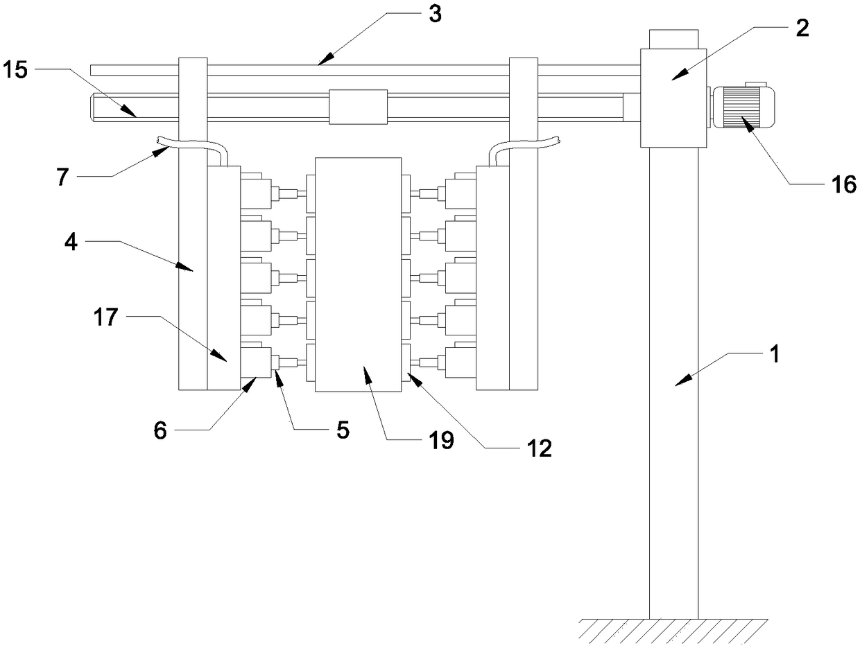
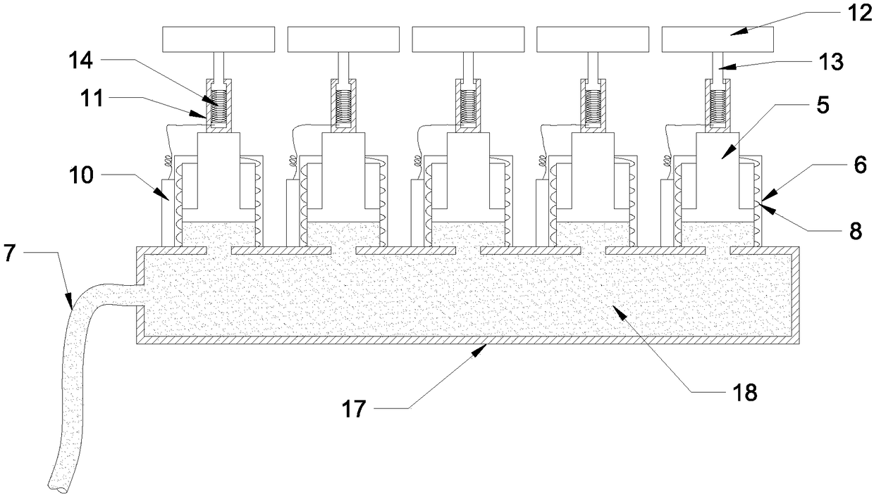
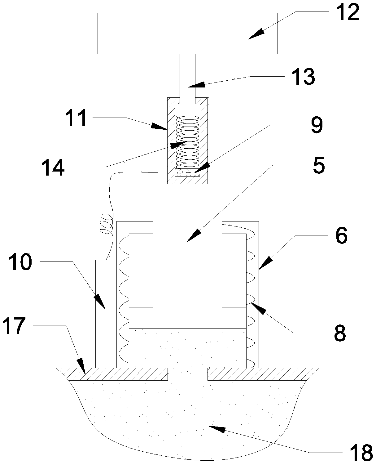
[0024] See Figure 1-3 , An automated mechanical fixture device, including a vertical support rod 1, on which is installed a slider 2 that can rotate and move up and down along the central axis of the support rod 1, and a horizontal guide rod 3 is fixed on the slider 2, The guide rod 3 is equipped with two clips 4 that can slide on the guide rod 3, and the two clips 4 are respectively provided with a driving mechanism that can make the clip 4 slide or stop on the guide rod 3; two clips 4 are respectively provided with a clamping force adjustment mechanism, the clamping force adjustment mechanism includes a plurality of hydraulic cylinders 6 with pistons 5, the hydraulic cylinders 6 are connected to a hydraulic pump through a pipe 7, and the hydraulic cylinders 6 on the two clamps 4 Pistons 5 are arranged oppositely; a conductive coil 8 is wound on the cylinder wall of the hydraulic cylinder 6, a pressure sensor 9 is provided on the free end of the piston 5 along the axis of the...

Embodiment 2

[0030] See Figure 1-3 , A clamping method of an automated mechanical clamp device, the operation steps are:

[0031] S1: According to the material and weight of the clip 19, use the formula pressure threshold to calculate the formula F=mg / f 0 Calculate the pressure threshold to be set;

[0032] S2: Adjust the height of the slider 2 on the support rod 1 and rotate the angle of the guide rod 3 so that the gripping object 19 is located between the two clips 4;

[0033] S3: Start the motor 16 to rotate the bidirectional screw 15 to adjust the relative position of the two clamps 4 on the guide rod 3 so that the free end of the piston 5 contacts the surface of the clamp 19, and the rotation of the motor 16 is stopped;

[0034] S4: Start the hydraulic pump to move the pistons 5 on both sides toward each other, and apply clamping force to the clamped object 19. When any pressure sensor 9 reaches the calculated F value, the relay control board 10 automatically connects to the circuit of the c...


PUM


Abstract

The invention relates to the field of mechanical clamps, and discloses an automatic mechanical clamp device and a clamping method. The automatic mechanical clamp device comprises a supporting rod. A sliding block with a guide rod is mounted on the supporting rod. Two clamp pieces with clamping force adjusting mechanisms are mounted on the guide rod. Each clamping force adjusting mechanism comprises multiple hydraulic cylinders with pistons. An electric conduction coil is wound around the barrel wall of each hydraulic cylinder. A pressure sensor is arranged at the free end of each piston. A relay control board is arranged on each electric conduction coil. Each replay control board is electrically connected with the corresponding pressure sensor. Liquid media of the hydraulic cylinders are magnetorheological fluid. According to the automatic mechanical clamp device, when clamping force reaches a threshold value set by the replay control boards, the replay control boards achieve circuit breakover of the electric conduction coils, a magnetic field is applied to the magnetorheological fluid, the magnetorheological fluid is converted into high viscosity and a low flowing state from a flowing state, and therefore the clamping force is stable; and clamped objects can be clamped and moved, and meanwhile the problem that too large clamping force is applied, and consequently the clamped objects are damaged can be avoided.

Description

Technical field [0001] The invention relates to the field of mechanical clamps, in particular to an automated mechanical clamp device and a clamping method. Background technique [0002] Manipulator is a kind of manipulator that can imitate certain movements and functions of human hands and arms. At present, due to the increase in production requirements of enterprises, the requirements for equipment performance have also increased, and production capacity has increased substantially. In this case, one of the effective ways to improve production capacity is to use a large number of manipulators, especially widely used in assembly line production. The use of manipulators to assist production is to improve efficiency and reduce errors; the other is to increase efficiency and reduce costs, so as to coordinate with production capacity. [0003] The existing manipulators mainly use mechanical clamps to grasp and transport the clamped objects, and move the clamped objects to the design...

Claims


Application Information

Patent Timeline
IPC IPC(8): B25J15/00
CPCB25J15/0019
Inventor 李典灿蒋俊威
Owner HUNAN MECHANICAL & ELECTRICAL POLYTECHNIC
Why Eureka
Try Eureka