Hot blast welding apparatus

A technology of hot air welding and hot air, which is applied in the field of hot air welding devices, can solve the problems of weak joint force, small pullout force, hydraulic oil leakage, etc., and achieve the effect of sufficient melting and strong pullout force

Pending Publication Date: 2019-01-04
上海皓威德自动化设备有限公司
View PDF0 Cites 3 Cited by
  • Summary
  • Abstract
  • Description
  • Claims
  • Application Information

AI Technical Summary

Problems solved by technology

As a result, after cooling, the joint force between the melted part and the unmelted part is not strong, so the overall pull-out resistan

Method used


Image

  • Hot blast welding apparatus
  • Hot blast welding apparatus
  • Hot blast welding apparatus

Examples


Embodiment Construction

[0035] The present invention is described in detail below in conjunction with accompanying drawing:

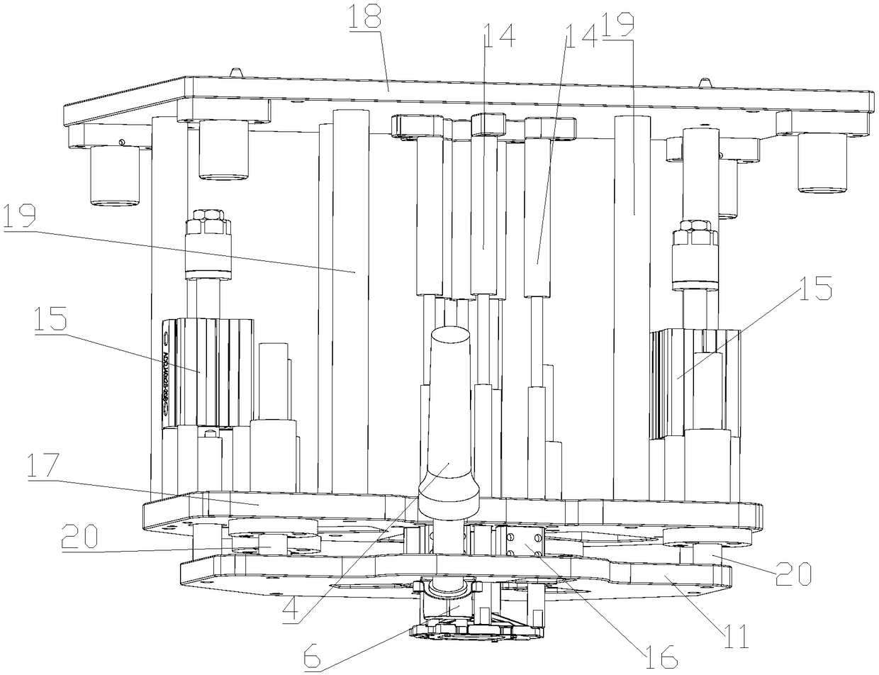
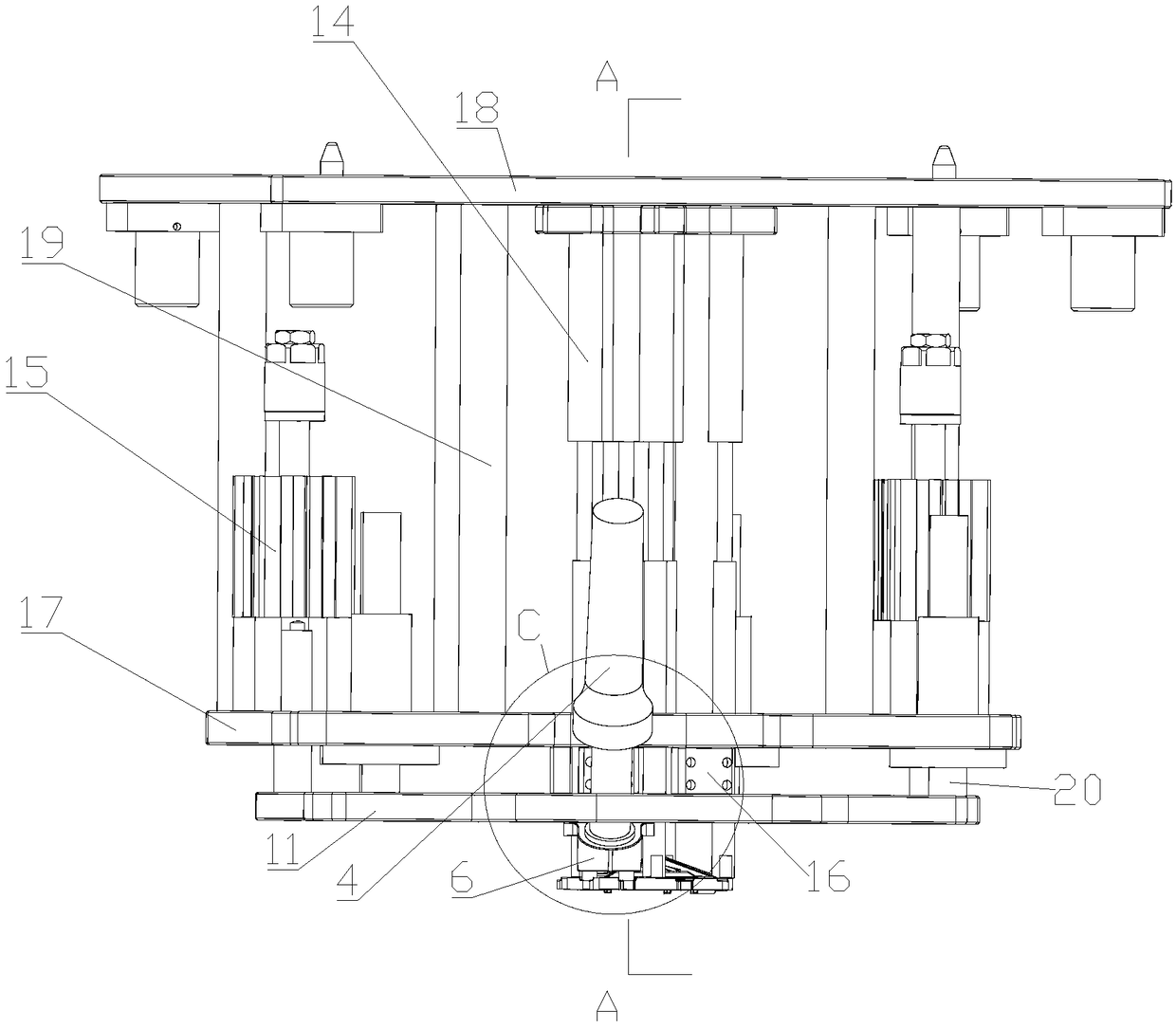
[0036] Such as figure 1 As shown, the hot air welding device of this embodiment is used for heat welding the welding point 1 of the parts to be welded, including: a hot air mechanism and a pressing mechanism, wherein the hot air mechanism is used to output hot air to the welding point 1 to soften the welding point 1 or Melted to a deformable degree, the pressing mechanism is set movably, and the melted or softened welding point 1 is deformed during the moving process.

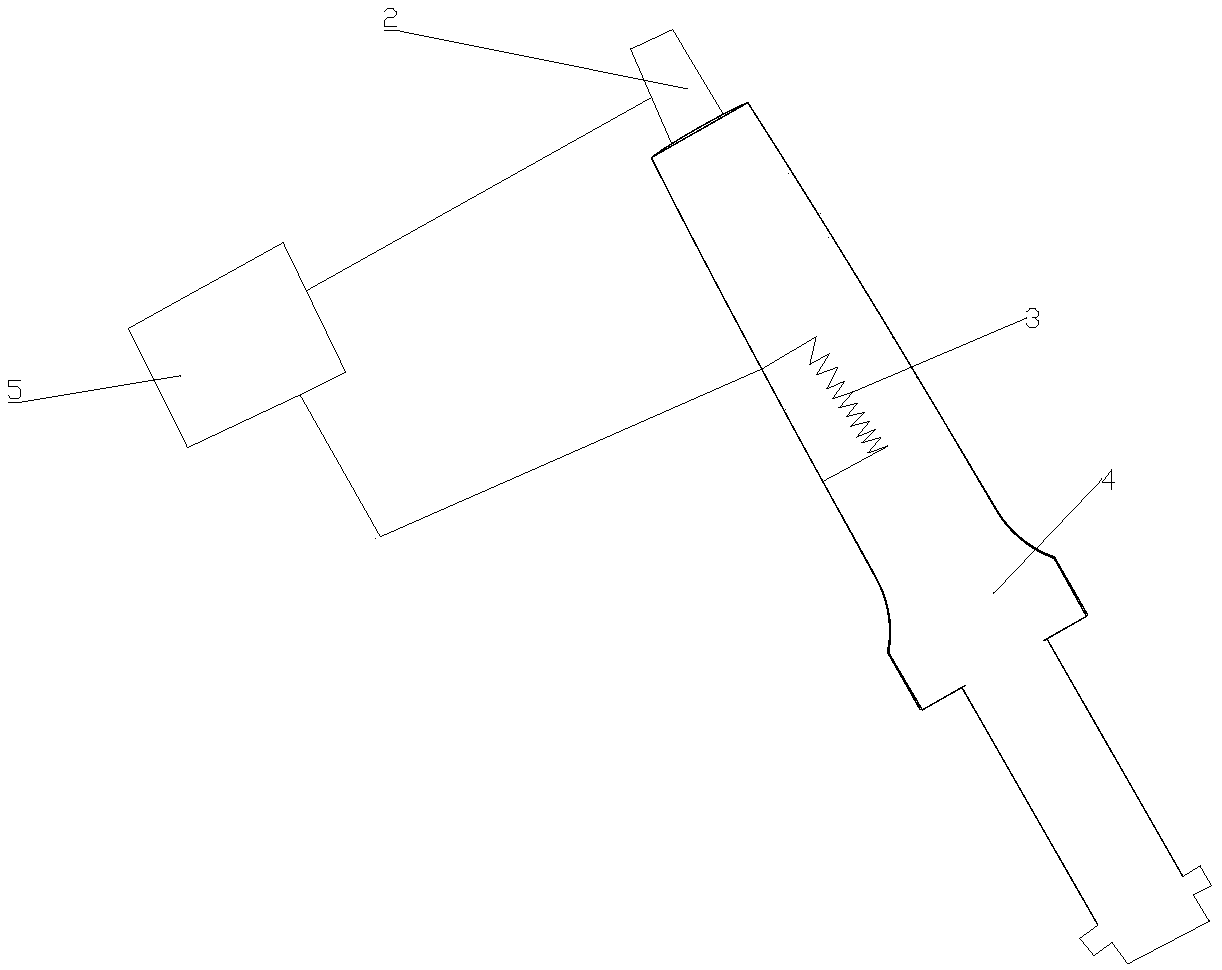
[0037] Such as figure 2 As shown, the hot air mechanism includes: an air source device 2, a heating element 3 and a channel 4, wherein the air source device 2 generates wind and delivers the wind to the channel 4, and the heating element 3 is used for heating the wind passing through the channel 4. heating. The heating element 3 can be arranged inside the channel 4 or outside the channel 4 as long as it can...


PUM


Abstract

The invention discloses a hot blast welding apparatus, comprising a hot blast mechanism and a pressing mechanism, wherein the hot blast mechanism is used for discharging hot air to a welding spot; thepressing mechanism is movably provided; the welding spot deforms during moving. Plastic with high hardness is ca be melted with hot air; melting of the plastic is more sufficient; the plastic that iswelded has better tensile strength which may be 5 times as high as the traditional case.

Description

technical field [0001] The invention relates to a hot air welding device. Background technique [0002] Some plastic products are relatively hard, such as parts for hydraulic brakes, which are close to metal texture. When this product is welded, the traditional method is contact hot melt welding. However, in contact-type thermal fusion, the contacted part is successfully thermally fused, but the untouched internal part will not be melted. As a result, after cooling, the bonding force between the melted part and the unmelted part is not strong, so that the overall pull-out resistance is small, and the product does not meet the requirements, such as the hydraulic oil leakage problem of parts for hydraulic brakes. Contents of the invention [0003] In order to solve the above technical problems, the present invention provides a hot air welding device. [0004] To achieve the above object, the present invention is achieved through the following technical solutions: [0005...

Claims


Application Information

Patent Timeline
IPC IPC(8): B29C65/02B29C65/10
CPCB29C65/02B29C65/10
Inventor 王书燕张鑫陈垒郭继岭
Owner 上海皓威德自动化设备有限公司
Why Eureka
Try Eureka