Weld joint of aluminum alloy member

A technology for aluminum alloy parts and welded joints, which is applied in the direction of welding/welding/cutting articles, vehicle parts, welding equipment, etc., and can solve problems such as insufficient strength of the welded part 105, reduced quality, difficulty in ensuring the thickness of the weld bead 107, etc.

Inactive Publication Date: 2012-03-28
HONDA MOTOR CO LTD +1
View PDF1 Cites 15 Cited by
  • Summary
  • Abstract
  • Description
  • Claims
  • Application Information

AI Technical Summary

Problems solved by technology

[0012] Combining these reasons, it is difficult to ensure that the weld thickness 108 of the weld bead 107
If the weld thickness 108 is insufficient, the strength of the welded portion 105 will be insufficient and the quality will be reduced.

Method used


Image

  • Weld joint of aluminum alloy member
  • Weld joint of aluminum alloy member
  • Weld joint of aluminum alloy member

Examples


experiment example

[0043] Experimental examples related to the present invention are described below. In addition, this invention is not limited to an experimental example.

[0044] Soldering is carried out under the following conditions.

[0045] ○Test materials:

[0046] Aluminum casting parts: AC4CH-T5 (ISO Al-Si7Mg), thickness 8mm

[0047] ·Extension parts of aluminum alloy: 6N01-T5, thickness 3.5mm

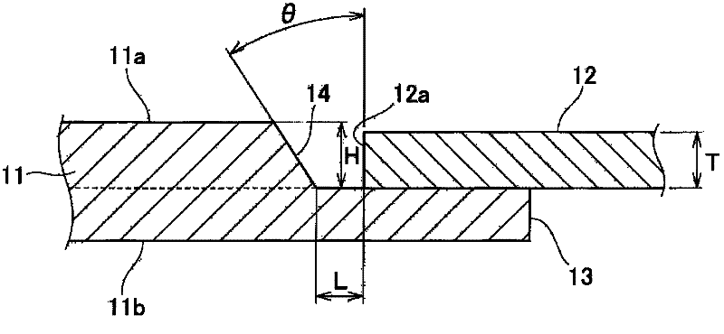
[0048] ○ Groove shape: figure 2 . Among them, the groove angle θ, the height H of the slope, and the root gap L are variables.

[0049] ○Welding conditions:

[0050] · Type: metal inert gas shielded welding

[0051] ・Filler wire: equivalent to A5356WY

[0052] ·Current: 230A

[0053] Rotation angle: 75°

[0054] ·Advance angle: 15°

[0055] · Welding speed: 70cm / min

[0056] ○: Verification of groove angle:

[0057] ·Height H of slope: 4.5mm

[0058] ·Root gap L: 5mm

[0059] Bevel angle θ: 10°, 15°, 30°, 45°, 50°

[0060] The joint efficiency was obtained for the obtained join...


PUM


Abstract

Disclosed is a weld joint of an aluminum alloy member formed by joining one end of a wrought material (12) to one end of a cast member (11). The cast member has a chamfer (14), and an inserting portion (13) which extends from the lower end of the chamfer (14) toward the distal end of the cast member along the lower surface of the wrought material. The distance (L) from the lower end of the chamfer to the end face (12a) at one end of the wrought material is set equal to 1.0-1.7 times of the thickness (T) of the wrought material, and the chamfer is inclined so that the angle of a groove between the chamfer and the end face (12a) at one end of the wrought material is 15-45 DEG.

Description

technical field [0001] The present invention relates to a welded joint in which one end of a stretch member made of one of aluminum and an aluminum alloy is joined to an end portion of a cast member of an aluminum alloy. Background technique [0002] In practice, there is provided a welded structure in which a stretched aluminum alloy member and an aluminum alloy cast member are joined. As a prior art related to such a welded structure, there is a technology disclosed in Patent Document 1. [0003] The welded structure described in Patent Document 1 is an auxiliary frame. The auxiliary frame is manufactured by welding the cover to the frame main body. The frame main body is a cast part of aluminum alloy, and the cover body is an extended part of aluminum alloy. [0004] The cover body is engaged with the frame main body all around. Because of the so-called full-circle welding, the welding length becomes significantly longer, and welding costs are high. Furthermore, the ...

Claims


Application Information

Patent Timeline
Patent Type & Authority Applications(China)
IPC IPC(8): B23K9/23B23K9/028B23K33/00B23K9/00B23K103/10B62D21/00
CPCB23K2203/10B23K2201/006B23K33/006B23K31/02B23K9/173B23K2203/18B23K9/23B62D21/11B23K33/008B23K9/0282B23K2101/006B23K2103/10B23K2103/18Y10T403/477
Inventor 矢羽羽隆宪高桥隼人平野大祐嶋田隆
Owner HONDA MOTOR CO LTD
Why Eureka
Try Eureka