A charge-type cavitation generating structure for supercavitating underwater vehicles

A technology for underwater navigating body and navigating body, applied in the direction of hull, hull design, transportation and packaging, etc., to achieve the effects of sufficient bubble volume, prolonged duration, stable and reliable bubbles

Inactive Publication Date: 2019-01-04
NANJING UNIV OF SCI & TECH
View PDF11 Cites 10 Cited by
  • Summary
  • Abstract
  • Description
  • Claims
  • Application Information

AI Technical Summary

Problems solved by technology

But this method also has the problem of not being...

Method used


Image

  • A charge-type cavitation generating structure for supercavitating underwater vehicles
  • A charge-type cavitation generating structure for supercavitating underwater vehicles

Examples


Embodiment Construction

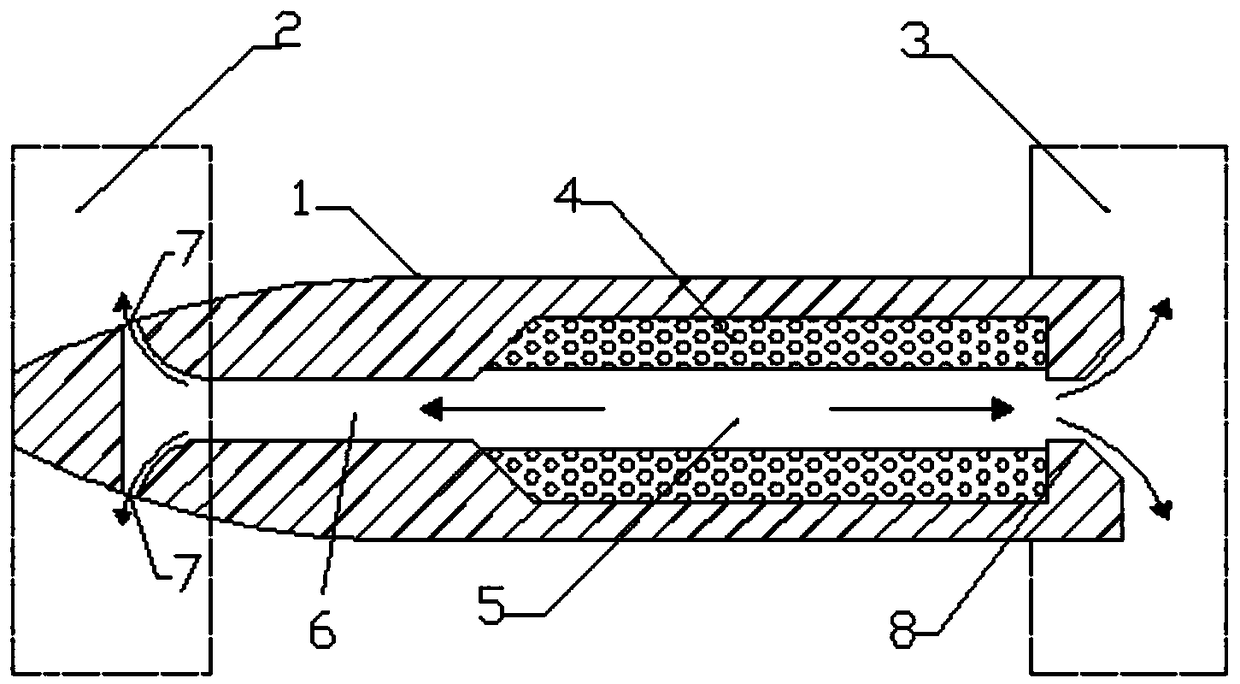
[0012] The present invention will be further described below by taking a simple supercavitating vehicle as an example in conjunction with the accompanying drawings.

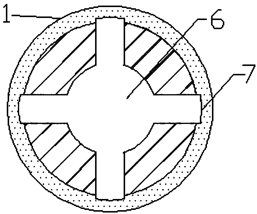
[0013] A charge type cavitation generating structure for a supercavitating underwater vehicle, the structure includes a vehicle 1, a propellant 4, a combustion chamber 5, a leading air pipe 6, a head exhaust hole 7, and a tail nozzle 8 .

[0014] combine figure 1 , figure 2 The middle and rear part of the vehicle 1 is hollow as the combustion chamber 5, and the inner wall of the combustion chamber 5 is tightly filled with the propellant 4, while the propellant 4 has a cylindrical cavity along the axis of the vehicle to facilitate the flow of gas generated by combustion. The front end of the combustion chamber is connected with the leading air pipe 6, and its diameter is slightly smaller than the cavity of the propellant 4. The front air duct 6 extends along the axis of the vehicle to the head part of the vehi...


PUM


Abstract

The invention discloses a charge-type cavitation generating structure for a supercavitation underwater vehicle. The interior hollow of the mid-rear section of the vehicle is used as the combustion chamber. The propellant is filled with the interior space along the inner wall of the combustion chamber, but a cylindrical cavity is left along the projectile axis. The front part of the combustion chamber is connected with the leading air duct, and the diameter of the leading air duct is slightly smaller than that of the propellant cavity. A lead air duct extends to that bullet head portion and isconnected with the nose vent hole and communicates with the external environment. A tail part of that combustion chamber is connected with a tail nozzle, and the tail nozzle communicates with the external environment in the form of a funnel. The scheme of the invention utilizes a large amount of gas and thrust generated during the combustion process of the propellant to generate cavitation, and prolongs the maintenance time of the supercavitation state of the high-speed underwater vehicle while continuously providing thrust.

Description

technical field [0001] The invention relates to the field of flow control, in particular to a charge-type cavitation generating structure for a supercavitating underwater vehicle. Background technique [0002] When the underwater vehicle moves at high speed, cavitation will occur under certain conditions. The cavitation phenomenon usually refers to that in the low-pressure area of ​​the liquid flow field, when the partial pressure reaches the saturated vapor pressure of the liquid, the liquid medium appears "cavitation" due to gasification. We call this "cavity" "cavitation" . Generally speaking, for an underwater vehicle surrounded by a flow field, when the length of the generated cavitation is smaller than the length of the vehicle, it is called a local cavitation; and when the length of the generated cavity reaches or exceeds the length of the vehicle, it is called Supercavitation. [0003] Since the supercavitation is larger than the vehicle body, it wraps the entire ...

Claims


Application Information

Patent Timeline
IPC IPC(8): B63B1/38
CPCB63B1/38B63B2001/382Y02T70/10
Inventor 赵子杰江代文张成龙
Owner NANJING UNIV OF SCI & TECH
Why Eureka
Try Eureka