
Multi-exercise rotary device

a rotary exercise and multi-exercise technology, applied in gymnastics, gyms, weights, etc., can solve the problems of cumbersome devices, dangerous and difficult to use in group classes or settings, and still fall short in adjustment and safety features, so as to simulate the jumping of a jump rope.

Inactive Publication Date: 2006-06-15
ROQUE ALDRIN
View PDF15 Cites 75 Cited by
  • Summary
  • Abstract
  • Description
  • Claims
  • Application Information

AI Technical Summary

Benefits of technology

[0011] In view of the foregoing disadvantages inherent in the different types of jump ropes including both the bar-type and without bar, jump rope simulators, including both the bar-type and without bar, and swinging air resistance exercise devices now present in the prior art, the new invention provides a new multi-exercise rotary device for providing both an aerobic and anaerobic exercise workout that can safely simulate the jumping of a jump rope as well as allow the user to perform non-traditional jump rope movements and positions. As a jump rope simulator, the present invention is able to offer a workout free from the constraints of actually having to jump over a physical rope, a major obstacle that must be overcome before a user can achieve any type of workout using a jump rope.
[0013] Furthermore, the planar surface of the invention's rotating member is able to provide a secondary progressive cooling effect, as a result of air displacement toward the user. For example, the rotating member can be an airfoil such as a propeller or combination of propellers arranged in a circular design, to help redirect air current. Since jump rope type exercises can be very intense, this cooling effect enhances performance by increasing comfort and helping prevent overheating or heat exhaustion of the user. Air current directed towards the user increases as the user works harder, providing for a more comfortable workout at higher intensities and longer durations. Furthermore, when the invention is used in opposite pairs the invention creates two separate currents of air, thereby doubling the cooling effect.

Problems solved by technology

Unfortunately, these devices have some drawbacks.
Jump ropes in general can be cumbersome, dangerous and difficult to use in group classes or settings, requiring ample floor space and ceiling height.
Jump rope simulators offer some options in the way of space restrictions and coordination constraints, but still fall short when it comes to adjustment and safety features.
In general, jump rope-type devices with separate handles are not as well suited for centrifugal weight adjustment as bar-type jump rope devices.
These devices can also be dangerous if there is a substantial increase in centrifugal weight, since there is a limited amount of impact absorption offered by the lumens or cord.
In addition, lumens or cord type jump rope simulator devices do not lend themselves to offering much in the way of adjustable rotational resistance.
Therefore, as the radial length increases, the chance of striking a person or object also increases.
Thus, safety becomes an issue.
Bar-type jump ropes only offer a limited range of motion and work a limited number of muscles.
This device fails to provide adjustable centrifugal weight for swinging.
Furthermore, since the device is used to perform exercises based on two different principals- linear resistance vs. repetitive plyometrics, shortening the length of the elastic would have a negative impact on the resistance band exercises, while the relatively long elastic becomes cumbersome when used as a swinging-type device, especially in confined quarters or group environments.

Method used


Image

  • Multi-exercise rotary device
  • Multi-exercise rotary device
  • Multi-exercise rotary device

Examples


Embodiment Construction

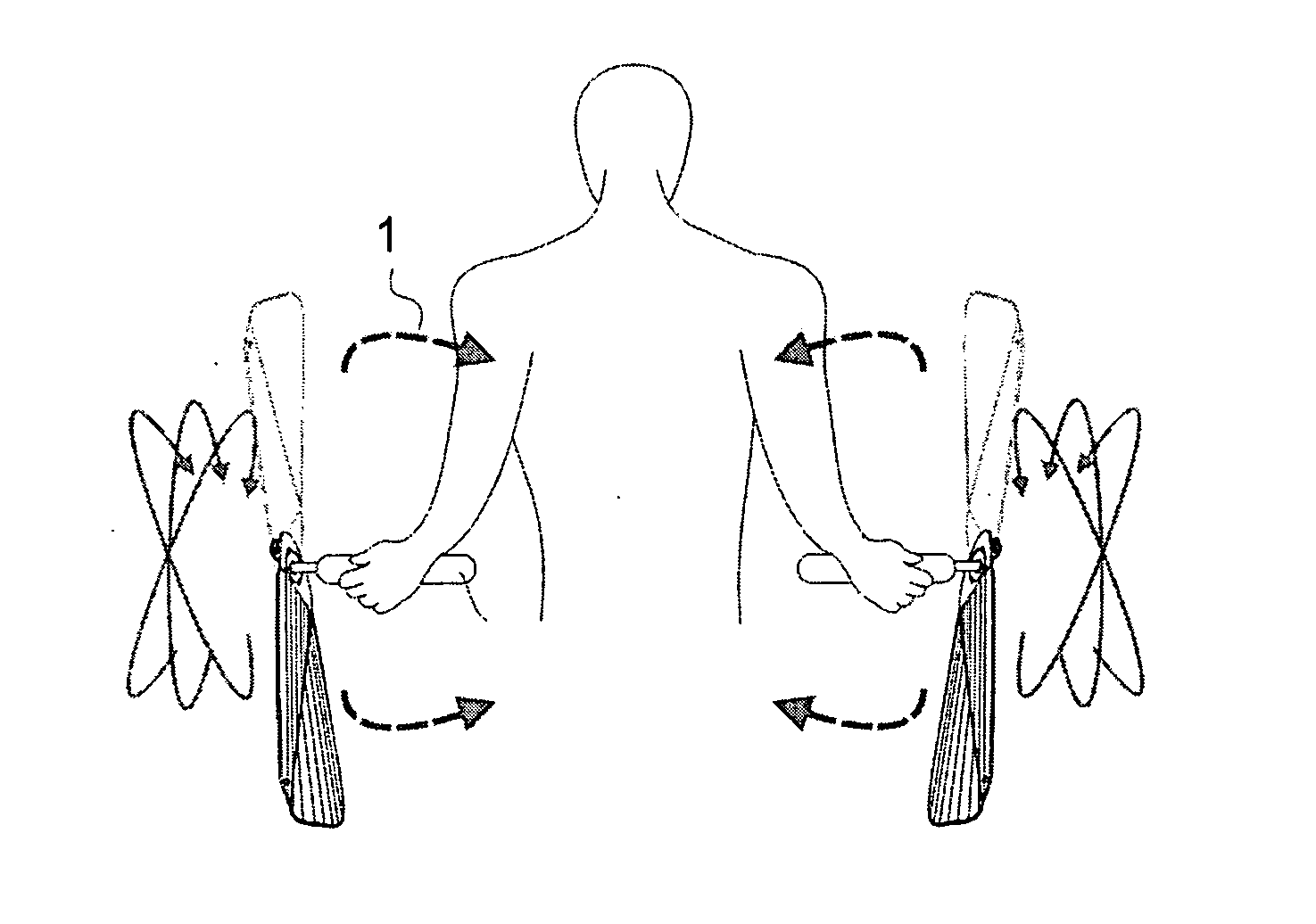
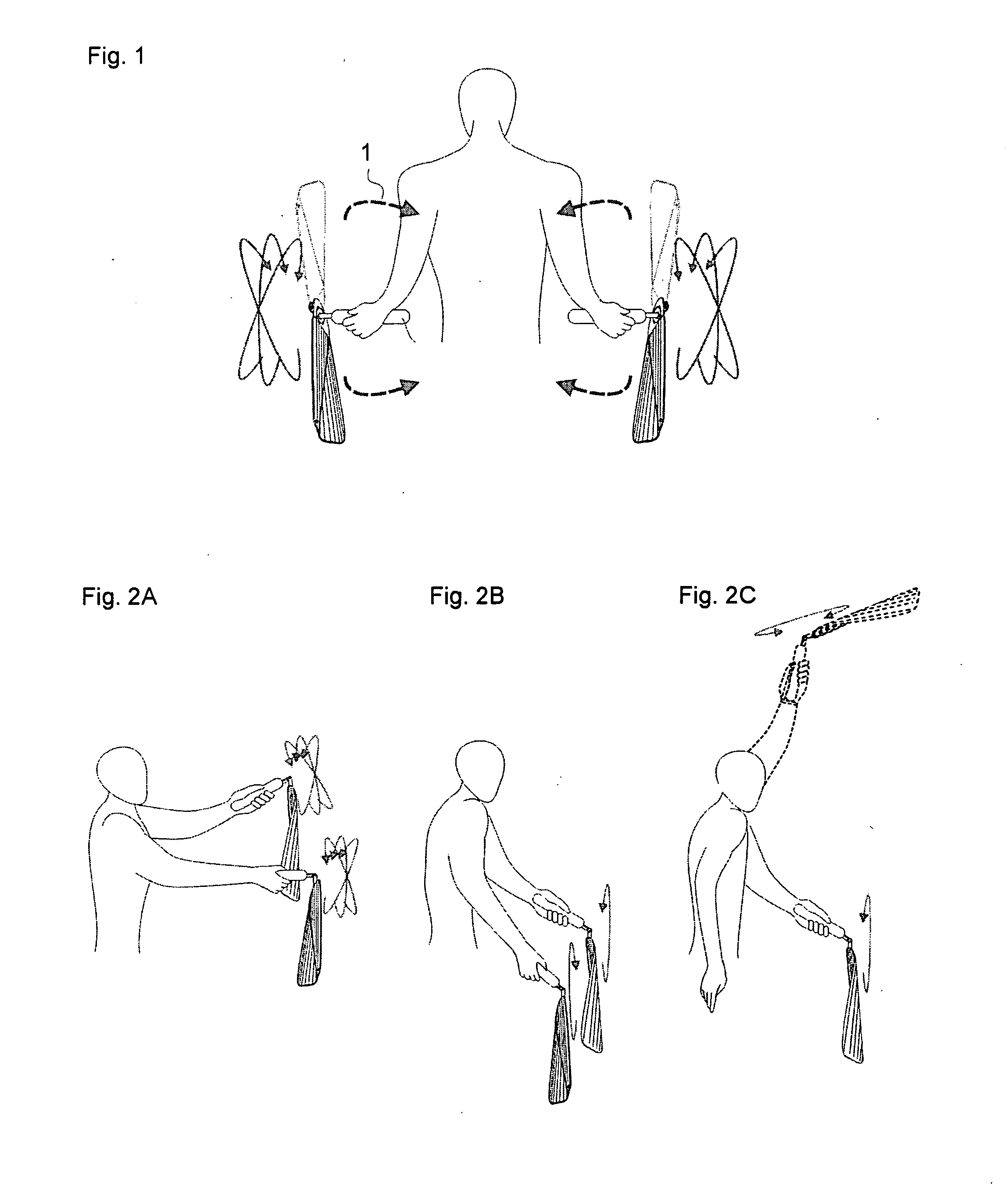
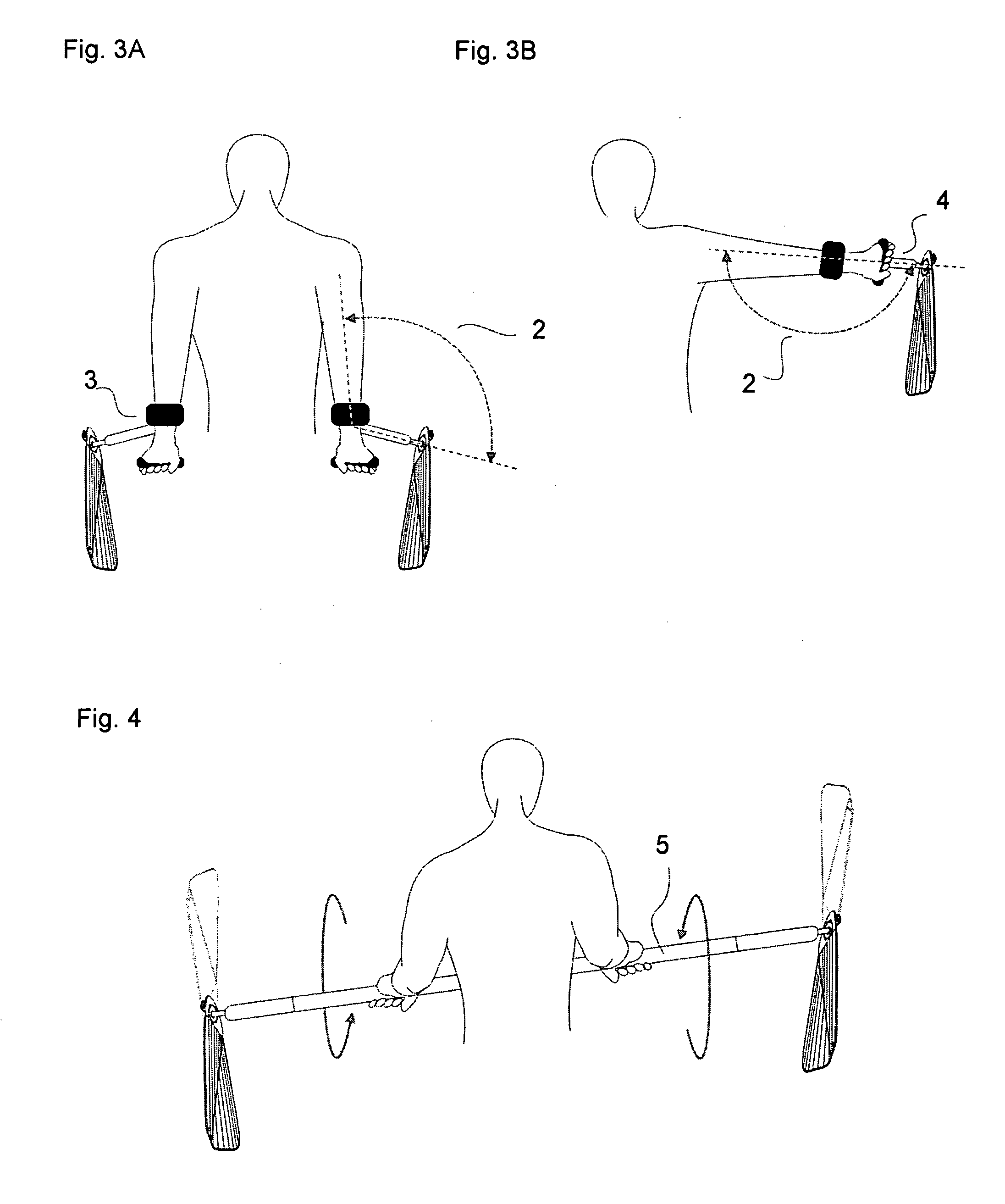
[0041] The present invention is a Multi-exercise rotary device supported by a body part, such as a hand or leg, of a user. The rotary exercise device provides a workout based on the user performing repetitive rotational movements so as to generate inertia in order to keep one or more of the component members of the device spinning (FIGS. 1-4). The Multi-exercise rotary device can be used to isolate a single appendage, such as a single hand-held unit in order to perform an exercise designed to rehabilitate a rotor cuff injury. When more than one rotary exercise device is used at the same time, the user can target multiple appendages in order to increase workout intensity, and obtain strength building, injury rehabilitation and cardiovascular benefits.

[0042] The rotary exercise device and cited attachments can be adjusted so that exercises can be performed in a variety of arm or leg positions to target specific muscles and muscle groups used to support or move the appendage, such as ...


PUM


Abstract

A multi-exercise rotary device, comprising: at least one elongate body-supported member, the body-supported member having a first end adapted to be supported by the body of the user, and a second end opposite the first end, at least one rotating member having a longitudinal axis that is at least semi-rigid, and which axis has a weight-biased distribution toward a distal end thereof; and a rotary mechanism for coupling the rotating member to a point on the body-supported member which is near the second end thereof. The rotary mechanism allows rotational movement of the rotating member about the longitudinal axis of the body-supported member. The rotary mechanism includes a device for constraining the angular movement between the weight-biased longitudinal axis of the rotating member and the longitudinal axis of the body-supported unit to be substantially only in a predetermined plane axially aligned with the body-supported member, and for constraining said plane from twisting with respect to the longitudinal axis of said body-supported member.

Description

BACKGROUND OF THE INVENTION [0001] 1. Field Of The Invention [0002] The present invention relates generally to rotary exercise devices, and more specifically, to a body supported rotary exercise device that can be used alone or in pairs, that is safe to use, especially in confined quarters or group environments, has minimal space requirements, and provides a plyometric upper and lower body workout through the use of adjustable centrifugal weight and / or adjustable rotary resistance. [0003] 2. Discussion of Background and Prior Art [0004] Jump ropes and jump rope simulators have been used for years and known in prior art as one of the most effective and powerful means of conditioning. They are known to provide amazing plyometric strength building and cardiovascular benefits, and are supported by studies claiming that regular use promotes increased metabolism, rapid fat loss and increased bone density. [0005] Both jump ropes, jump rope simulators and air resistance training devices her...

Claims


Application Information

Patent Timeline
Patent Type & Authority Applications(United States)
IPC IPC(8): A63B23/16A63B5/20A63B15/00
CPCA63B15/00A63B21/0088A63B21/015A63B21/22A63B23/12A63B21/00061A63B21/00069A63B21/0004A63B23/03525A63B23/03541A63B21/4017A63B21/4035A63B21/4043A63B21/4049
Inventor ROQUE, ALDRIN
Owner ROQUE ALDRIN
Learn More