An unmanned aerial vehicle automatic airport system
A UAV and airport technology, applied in the field of UAV automatic airport system, can solve the problems of low positioning accuracy of UAV, low degree of automation of ground handling system, large apron size, etc.
- Summary
- Abstract
- Description
- Claims
- Application Information
AI Technical Summary
Problems solved by technology
Method used
Image
Examples
Embodiment 1
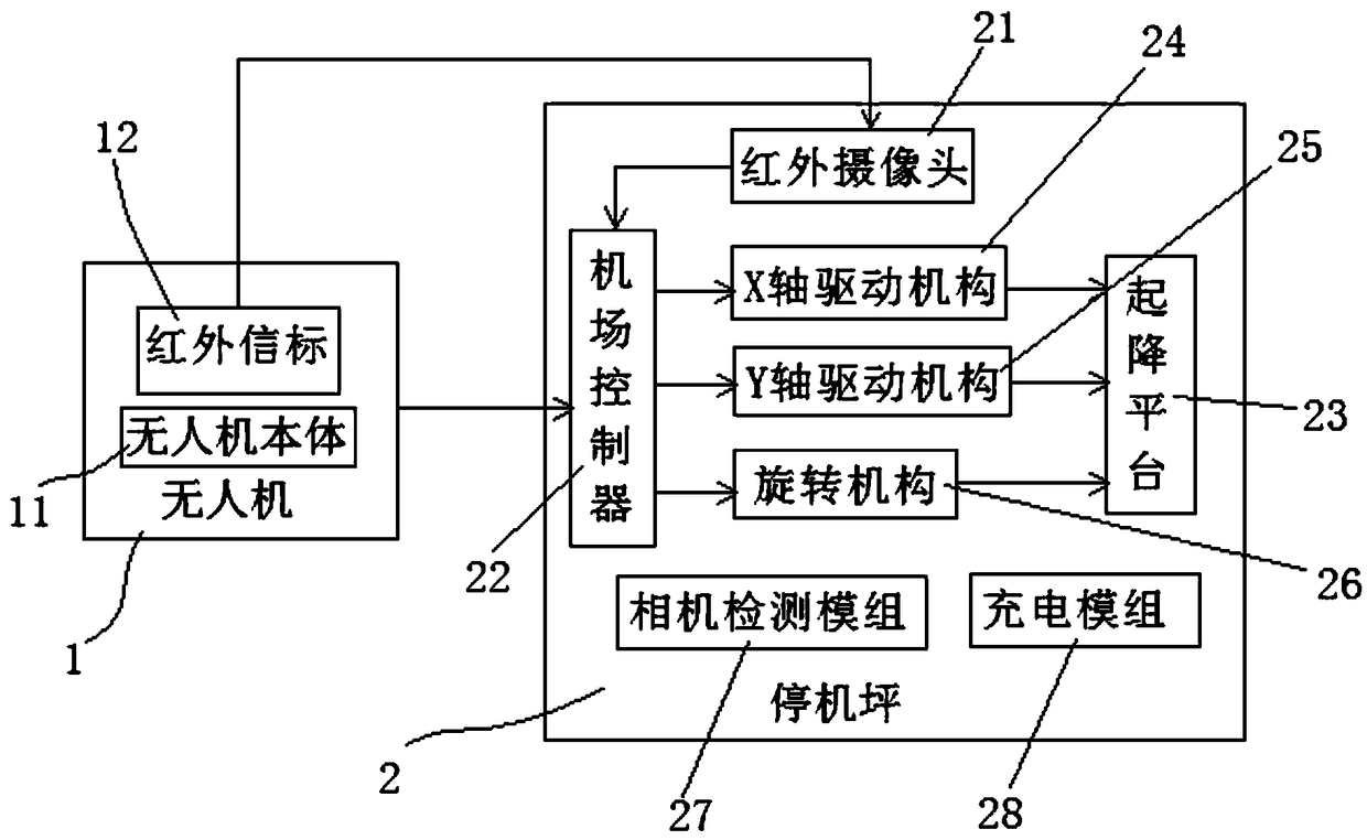
[0066] Such as figure 1 As shown, a UAV automatic airport system includes UAV 1 and apron 2; the UAV 1 includes a UAV body 11 and an infrared beacon 12, and the infrared beacon 12 is installed on an unmanned Machine body 11 abdomen.
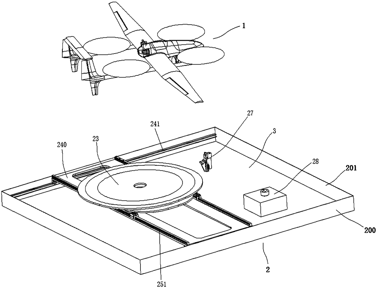
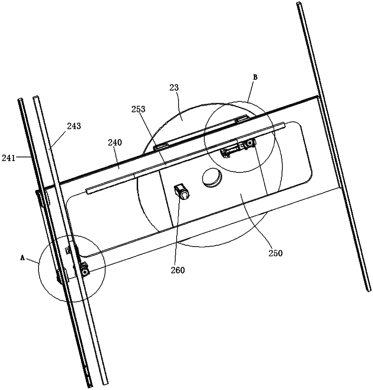
[0067] Such as figure 1 , figure 2 As shown, the apron 2 includes an apron frame 20 installed on the bottom surface 4, an infrared camera 21, an airport controller 22, a landing platform 23, an X-axis drive mechanism 24, a Y-axis drive mechanism 25 and a rotation mechanism 26, The take-off and landing platform 23 is circular, and the apron 2 is square. The apron frame 20 is a cuboid structure surrounded by two X-axis frames 200 and two Y-axis frames 201 connected end to end, and the X-axis driving mechanism 24 and the Y-axis driving mechanism 25 respectively drive the landing platform 23 moves along the length direction of the X-axis frame 200 and the Y-axis frame 201 , the rotating mechanism 26 drives the lifting platform 23 to rotate, and ...
Embodiment 2
[0092] Such as figure 1 As shown, a UAV automatic airport system includes UAV 1 and apron 2; the UAV 1 includes a UAV body 11 and an infrared beacon 12, and the infrared beacon 12 is installed on an unmanned Machine body 11 abdomen.
[0093] Such as figure 1 , figure 2 As shown, the apron 2 includes an apron frame 20 installed on the bottom surface 4, an infrared camera 21, an airport controller 22, a landing platform 23, an X-axis drive mechanism 24, a Y-axis drive mechanism 25 and a rotation mechanism 26, The apron frame 20 is a cuboid structure surrounded by two X-axis frames 200 and two Y-axis frames 201 connected end to end, and the X-axis driving mechanism 24 and the Y-axis driving mechanism 25 respectively drive the landing platform 23 moves along the length direction of the X-axis frame 200 and the Y-axis frame 201 , the rotating mechanism 26 drives the lifting platform 23 to rotate, and the infrared camera 21 is installed on the lifting platform 23 .
[0094] Whe...
PUM
 Abstract
Description
Claims
Application Information
 - R&D
- Intellectual Property
- Life Sciences
- Materials
- Tech Scout
- Unparalleled Data Quality
- Higher Quality Content
- 60% Fewer Hallucinations
Browse by: Latest US Patents, China's latest patents, Technical Efficacy Thesaurus, Application Domain, Technology Topic, Popular Technical Reports.
© 2025 PatSnap. All rights reserved.Legal|Privacy policy|Modern Slavery Act Transparency Statement|Sitemap|About US| Contact US: help@patsnap.com


