
Engine cooling system

An engine cooling and engine technology, applied in the direction of engine cooling, engine components, combustion engines, etc., can solve problems such as increased heat loss, incomplete combustion, and increased fuel consumption, so as to reduce fuel consumption and emissions, and quickly warm up fuel consumption , the effect of reducing friction work

Inactive Publication Date: 2019-01-04
CHONGQING CHANGAN AUTOMOBILE CO LTD
View PDF4 Cites 8 Cited by
  • Summary
  • Abstract
  • Description
  • Claims
  • Application Information

AI Technical Summary

Problems solved by technology

When the engine starts cold, due to the low temperature of the intake system and the cylinder, it is difficult for the gasoline to evaporate completely, which will cause incomplete combustion, cause a large amount of C and H emissions, and form pollution
At the same time, because the fuel is difficult to evaporate and the combustion condition is poor, it also causes the problem of increasing the amount of fuel.
In addition, the cooling water temperature of the engine is also low during the warm-up process, and the heat taken away by the cooling water of the engine increases, which increases the heat loss and further aggravates the aforementioned problems of pollution emissions and increased fuel consumption.
Another problem is that when the engine starts cold, the temperature is low, and the lubricating oil cannot work effectively, resulting in greater friction of the internal moving parts of the engine.

Method used


Image

  • Engine cooling system
  • Engine cooling system
  • Engine cooling system

Examples


Embodiment Construction

[0021] Below in conjunction with accompanying drawing and specific embodiment the present invention is described in further detail:

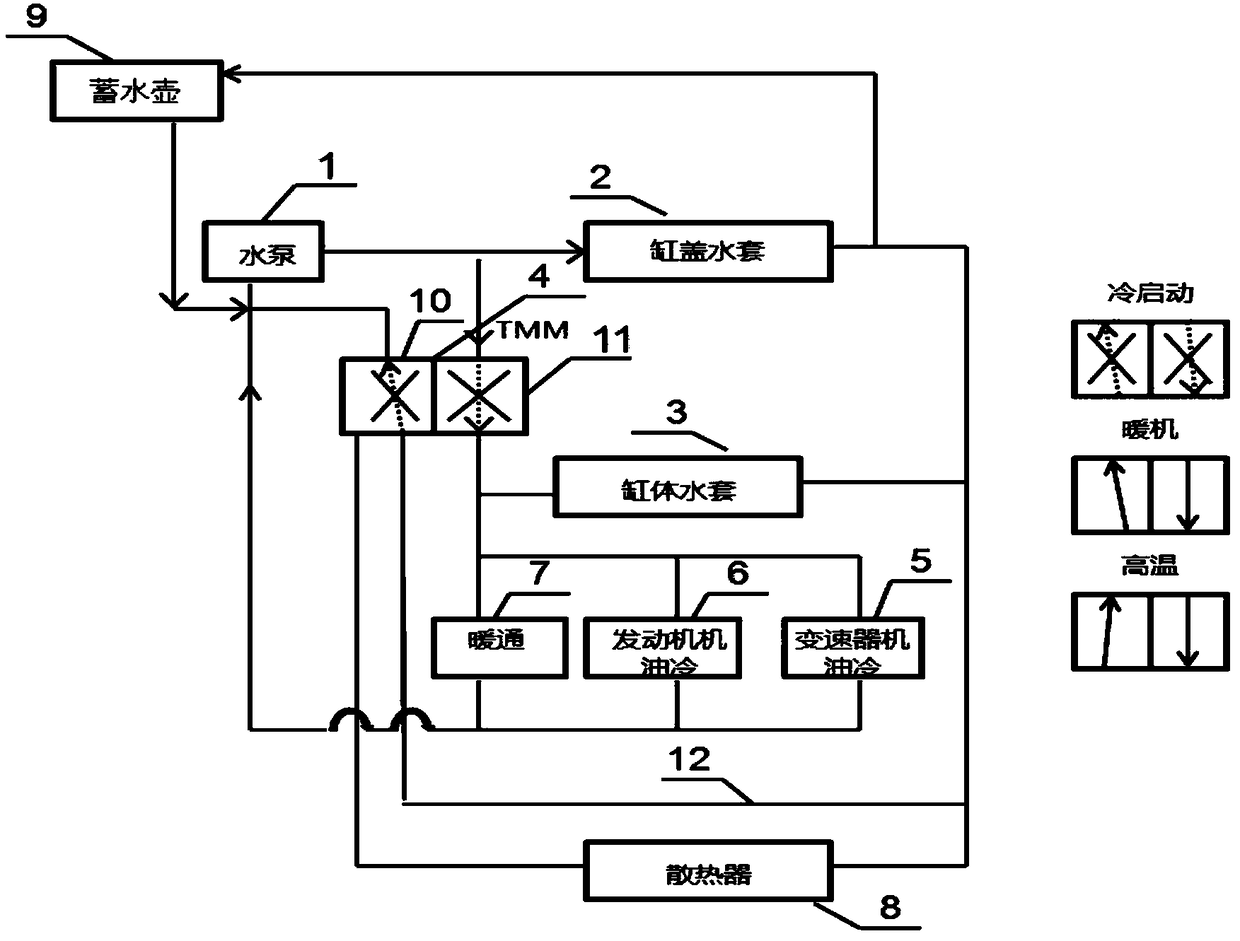
[0022] The structure of this system can be found in figure 1 , This system includes the components involved: engine water pump 1, cylinder block water jacket 3, cylinder head water jacket 2, thermostat 4, HVAC 7, radiator 8, engine oil cooler 6, transmission oil cooler 5.

[0023] Among them, the thermostat 4 adopts thermal management type thermostat TMM (thermal management module), such as Qufu Tianbo EA888-3, ITW Changan Automobile 1306040-NE01, which is equipped with a high pressure chamber 11 and a low pressure chamber 10, and the high pressure chamber and the The low-pressure chambers are not connected to each other. The high-pressure chamber is equipped with a channel that can be opened and closed, which can be selectively switched on and off according to the load requirements. The low-pressure cavity is equipped with two channels that can...


PUM


Abstract

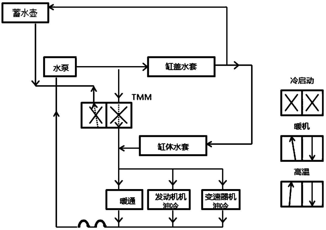
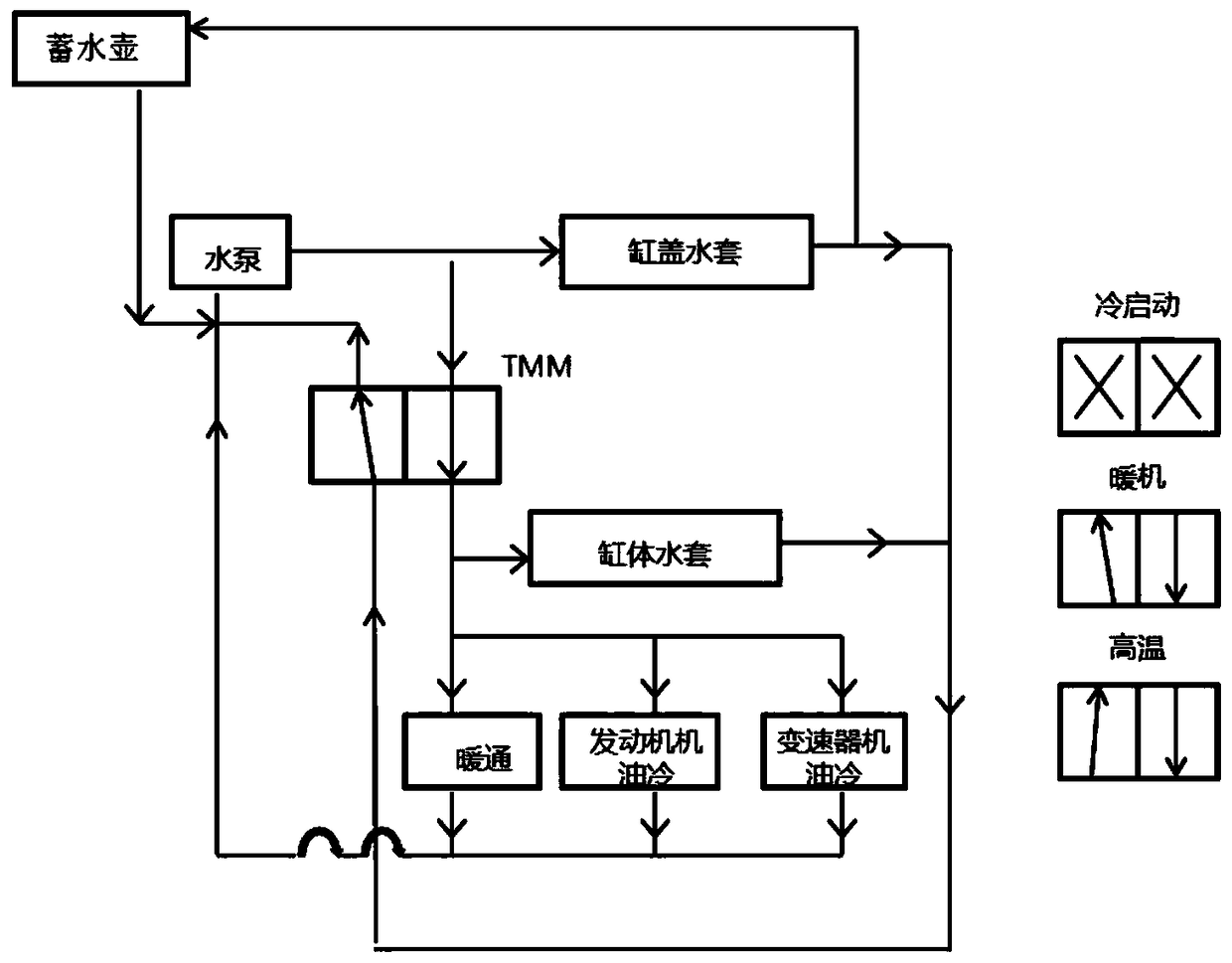
The invention provides an engine cooling system. The engine cooling system comprises an engine cylinder body, a cylinder body water sleeve, a cylinder cover water sleeve, a temperature conditioning device, a heating and ventilating device, an engine oil cooler and a water storing kettle. According to the engine cooling system, a switch is controlled based on the selection of the temperature conditioner, and the flowing direction of cooling water can be switched based on the load of an engine, so that rapid machine heating and oil consumption reducing can be realized; the cylinder cover water sleeve and the cylinder body water sleeve are connected in series in the engine cold starting stage, and the cooling water can be heated twice in one circulation, so that the temperature increasing speed of the cooling water is maximized; in addition, the oil cooler performs heat exchanging, so that the temperature of engine oil can be rapidly increased, the frictional power of the engine is reduced, and the oil consumption and emission can be reduced; the cylinder cover water sleeve and the cylinder body water sleeve are connected in parallel in the high-temperature engine heating and high-temperature stages, the water flow rate of the engine is increased to the maximum, and the water flow rate of the cylinder body and the cylinder cover can be controlled, so that the cylinder body and thecylinder cover can reach the optimal temperature, and as a result, engine knocking can be reduced, and the oil consumption can be decreased.

Description

technical field [0001] The invention belongs to the technical field of automobile engines, in particular to an engine cooling system. Background technique [0002] Engine warm-up refers to the process in which the temperature of the engine body rises from low temperature to normal operating temperature. When the engine starts cold, due to the low temperature of the intake system and the cylinder, it is difficult for gasoline to evaporate completely, which will cause incomplete combustion, cause a large amount of C and H emissions, and form pollution. At the same time, due to the difficulty of fuel evaporation and poor combustion conditions, the problem of additionally increasing the amount of fuel is caused. In addition, the cooling water temperature of the engine is also low during the warm-up process, and the heat taken away by the cooling water of the engine increases, which increases the heat loss and further aggravates the aforementioned problems of pollution emissions...

Claims


Application Information

Patent Timeline
Patent Type & Authority Applications(China)
IPC IPC(8): F01P3/02F01P7/16F01P11/08F02N19/10F16H57/04F02G5/00
CPCF01P3/02F01P7/165F01P11/08F02G5/00F02N19/10F16H57/0412Y02T10/12
Inventor 欧阳梅余小东曾庆强谢琰
Owner CHONGQING CHANGAN AUTOMOBILE CO LTD
Learn More