Embedded hydraulic pump

A hydraulic pump and embedded technology, applied in the field of hydraulic pumps, can solve the problems of increasing installation space, easy oil leakage of hydraulic pumps, easy burning of hydraulic pumps, etc., to improve heat dissipation capacity, increase installation space, and not easy to burn pumps Effect

Pending Publication Date: 2019-01-04
AVIC LIYUAN HYDRAULIC
View PDF0 Cites 0 Cited by
  • Summary
  • Abstract
  • Description
  • Claims
  • Application Information

AI Technical Summary

Problems solved by technology

[0004] First of all, since the existing hydraulic pump is installed outside the system, the volume of the system will be increased, so that the installation of the system requires more installation space; secondly, the oil circuit of the existing hydraulic pump is connected to the system through a pipe joint, which increases the risk of oil leakage. point, causing the hydraulic pump to easily leak oil; again, the pump cavity of the existing hydraulic pump is sealed by the shell, and the oil in the pump cavity enters and exits through the oil return port, and the oil return is small, and the heat in the pump cavity is difficult to quickly return to The oil port is taken away, the hydraulic pump is easy to burn the pump
[0005] Therefore, the existing hydraulic pump has the defects of increasing the installation space required for system installation, easy oil leakage and easy pump burning

Method used


Image

  • Embedded hydraulic pump
  • Embedded hydraulic pump
  • Embedded hydraulic pump

Examples


Embodiment Construction

[0016] The present invention will be further described below in conjunction with the accompanying drawings and embodiments, but not as a basis for limiting the present invention.

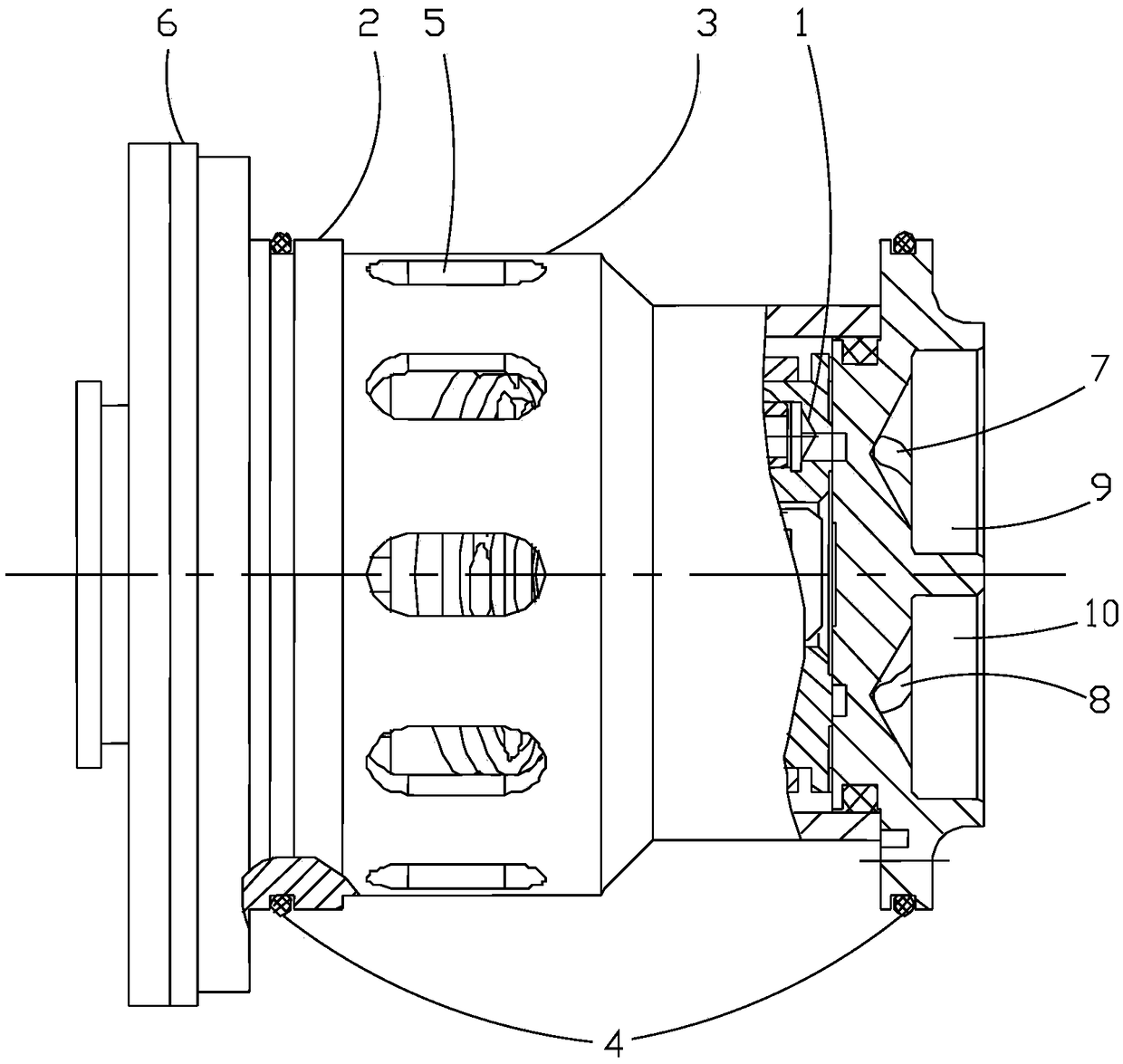
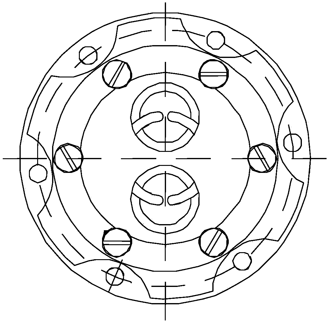
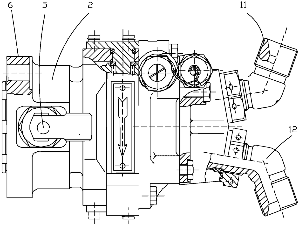
[0017] Example. Embedded cartridge hydraulic pumps, such as figure 1 As shown, it includes a body 1, which is provided with a housing 2 in the shape of a revolving body. Both ends of the housing 2 are provided with sealing rings 4. Between the two sealing rings 4, there is a seal on the peripheral surface of the housing 2 The annular concave surface 3 is provided with a through hole 5 on the side wall of the housing 2, the through hole 5 is connected with the pump chamber of the body 1, one end of the housing 2 is provided with a mounting edge 6, and the other end of the housing 2 An oil inlet 7 and an oil outlet 8 are provided, the oil inlet 7 is provided with an oil inlet sink hole 9 , and the oil outlet 8 is provided with an oil outlet sink hole 10 . The body 1 is the part of the existing hydr...


PUM


Abstract

The invention discloses an embedded hydraulic pump. The embedded hydraulic pump comprises a main body (1); the main body (1) is provided with a revolving body type shell (2); sealing rings (4) are arranged at two ends of the shell (2); an annular concave surface (3) positioned on the peripheral surface of the shell (2) is arranged between the two sealing rings (4); the annular concave surface (3)is provided with a through hole (5) positioned on the side wall of the shell (2); the through hole (5) is connected with a pump cavity of the main body (1); a mounting edge (6) is arranged at one endof the shell (2); an oil inlet (7) and an oil outlet (8) are arranged at the other end of the shell (2); an oil inlet counter bore (9) is formed in the oil inlet (7); and an oil outlet counter bore (10) is formed in the oil outlet (8). The embedded hydraulic pump has the advantages of no adding of the mounting space needed for system installation, difficult oil leakage and difficult pump burnout.

Description

technical field [0001] The invention belongs to the field of hydraulic pumps or hydraulic motors, in particular to an embedded plug-in hydraulic pump. Background technique [0002] As one of the core power components and actuators of the hydraulic control and transmission system (hydraulic control and transmission system referred to as the system), the hydraulic pump or hydraulic motor is crucial to the system. It provides high-pressure hydraulic energy or Mechanical energy enables the system to adjust in real time according to instructions, ensuring the completion and safety of system tasks. From a structural point of view, the hydraulic pump is a hydraulic motor. From the specific use status, when the hydraulic pump is driven by the motor to output hydraulic energy, the hydraulic pump realizes the function of the hydraulic pump. When the hydraulic pump outputs mechanical energy through the action of pressure oil, the hydraulic pump The pump fulfills the function of the hy...

Claims


Application Information

Patent Timeline
Patent Type & Authority Applications(China)
IPC IPC(8): F04B53/16F04B53/22F04B53/08
CPCF04B53/16F04B53/08F04B53/22
Inventor 谯维智杨光武陆红林林昌贤孙凯
Owner AVIC LIYUAN HYDRAULIC
Why Eureka
Try Eureka