Redundancy control type hydraulic station

A technology of redundant control and hydraulic station, which is applied in fluid pressure actuation devices, fluid pressure actuation system components, mechanical equipment, etc., can solve the problems affecting the production sequence and the unsolved high-pressure filter pollution-holding capacity, etc., to achieve Effects of avoiding production loss or production accidents, protecting the environment, and increasing reliability

Pending Publication Date: 2019-01-04
成都赛来机械有限公司
View PDF2 Cites 4 Cited by
  • Summary
  • Abstract
  • Description
  • Claims
  • Application Information

AI Technical Summary

Problems solved by technology

[0003] But neither of them solves the problem. When the high-pressure filter has insufficient dirt-holding capacity and an alarm occurs, it is impossible to switch to another group to continue working. It can only be stopped for replacement, which affects the normal production sequence.

Method used


Image

  • Redundancy control type hydraulic station
  • Redundancy control type hydraulic station
  • Redundancy control type hydraulic station

Examples


Embodiment 1

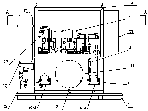
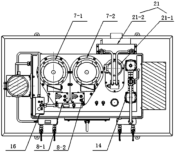
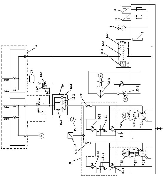
[0036] Such as Figure 1~Figure 3 As shown, the redundant control hydraulic station includes a main body of the hydraulic station, the main body of the hydraulic station includes a fuel tank 1, and two pump groups 7, a control oil circuit block 8, a pressure regulating valve group 19, High-pressure filter 16, oil return filter 14; the two pump groups 7, control oil circuit block 8, pressure regulating valve group 19, high-pressure filter 16, and oil return filter 14 are connected in sequence; the two pump groups 7 communicate with the two oil outlets of the oil tank 1 respectively, and the oil return filter 14 communicates with the oil return port of the oil tank 1 . The control oil circuit block 8 includes two parallel control oil circuit blocks 8, and the two control oil circuit blocks 8 are respectively connected with two parallel pump sets 7, and the high pressure filter 16 includes a high pressure filter switching valve 16-1 and the first high-pressure filter 16-2 and th...

Embodiment 2

[0047] This embodiment is improved on the basis of Embodiment 1. The improvement is that: the oil return filter 14 includes an oil return filter switching valve 14-1 and a valve connected to the oil return filter switching valve 14-1. The first oil return filter 14-2 and the second oil return filter 14-3; the first oil return filter 14-2 and the second oil return filter 14-3 are connected in parallel, and the first oil return filter The oil outlets of the filter 14-2 and the second oil return filter 14-3 communicate with the oil return port of the mailbox respectively.

[0048] The switching valve of the oil return filter 14 is integrated with the oil return filter 14, and the switching valve of the oil return filter 14 includes two valve positions, corresponding to the first oil return filter 14 and the second oil return filter respectively 14. When the valve position is switched, the switching of the first oil return filter 14 and the second oil return filter 14 is completed...

Embodiment 3

[0051] This embodiment is improved on the basis of Embodiment 1 or 2, and the improvement is that: the hydraulic station also includes an accumulator 17 and an accumulator control oil circuit block 818 connected to the accumulator 17, so The accumulator control oil block 818 includes a first cut-off valve 18-1, a second cut-off valve 18-2 and a first overflow valve 18-3; the first cut-off valve 18-1 and the second cut-off valve 18 -2. The first relief valve 18-3 communicates, and the second cut-off valve 18-2 and the first relief valve 18-3 are connected in parallel; the oil outlet of the high-pressure filter 16 is connected to the first cut-off valve 18-1; the accumulator 17 communicates with the second cut-off valve 18-2 and the first overflow valve 18-3. The hydraulic oil that passes through the high-pressure filter 16 enters the accumulator 17 through the accumulator control oil circuit block 818. When the power supply of the hydraulic station is cut off, the energy stored...


PUM


Abstract

The invention discloses a redundancy control type hydraulic station. The redundancy control type hydraulic station comprises a hydraulic station body, wherein the hydraulic station comprises an oil tank; two pump sets, control oil channel blocks, a pressure regulating valve set, high-pressure filters and an oil returning filtering device which are sequentially connected are mounted in the hydraulic station body; each high-pressure filter comprises a high-pressure filter switching valve, a first high-pressure filter and a second high-pressure filter; the first high-pressure filters and the second high-pressure filters communicate with the high-pressure filter switching valves; the first high-pressure filters and the second high-pressure filters are connected in parallel; the control oil channel blocks communicate with a high-pressure switching valve; an oil outlet of each first high-pressure filter and an oil outlet of each second high-pressure filter correspondingly communicate with anoil inlet of the pressure regulating valve set. According to the redundancy control type hydraulic station, two pump sets, two control oil channel blocks and two high-pressure filters are designed, so that the situation with high requirement on reliability of a hydraulic station applies.

Description

technical field [0001] The invention relates to a material drilling tool in the assembly process, in particular to a redundant control hydraulic station. Background technique [0002] Conventional hydraulic station has only one set of motor, pump system, one set of high pressure filter and one set of oil return filter. When the motor and pump system fail, there is no spare motor and pump system, so they can only be shut down for maintenance immediately, which affects production efficiency. The invention patent application document with the application number "201310580380.6" and the name "mine hoist hydraulic station" discloses a hydraulic station, which consists of two double-connected variable vane pumps, two sets of pressure regulating valve groups, and a set of The reversing valve group and a set of control oil circuit blocks are composed of redundancy, which realizes non-stop maintenance. The patent application document with application number "201420561898.5" and tit...

Claims


Application Information

Patent Timeline
Patent Type & Authority Applications(China)
IPC IPC(8): F15B21/08F15B1/02F15B21/04
CPCF15B21/08F15B1/02F15B21/04
Inventor 曾静王伟徐国强
Owner 成都赛来机械有限公司
Why Eureka
Try Eureka