Multi-gear variable speed drawing machine

A drawing machine and gear lever technology, applied in mechanical equipment, transmission parts, gear transmissions, etc., can solve the problems of motor power waste and power waste, and achieve the effects of reducing energy consumption, improving economic benefits and improving efficiency

Pending Publication Date: 2019-01-04
TJK MACHINERY TIANJIN
View PDF0 Cites 2 Cited by
  • Summary
  • Abstract
  • Description
  • Claims
  • Application Information

AI Technical Summary

Problems solved by technology

At present, the drawing machines on the market have self-made gearboxes and direct-connected reducers to achieve power output. The above-mentioned methods all have only one reduction ratio. In the case of a wide range of steel bar diameters, there is only one structure with a reduction ratio. , the power of the motor will be greatly wasted. If the drawing machine can draw large-diameter steel bars, its power will inevitably be wasted when drawing small-diameter steel bars.

Method used


Image

  • Multi-gear variable speed drawing machine
  • Multi-gear variable speed drawing machine

Examples


Embodiment Construction

[0026] The technical solutions of the present invention will be further described below in conjunction with the accompanying drawings and through specific embodiments.

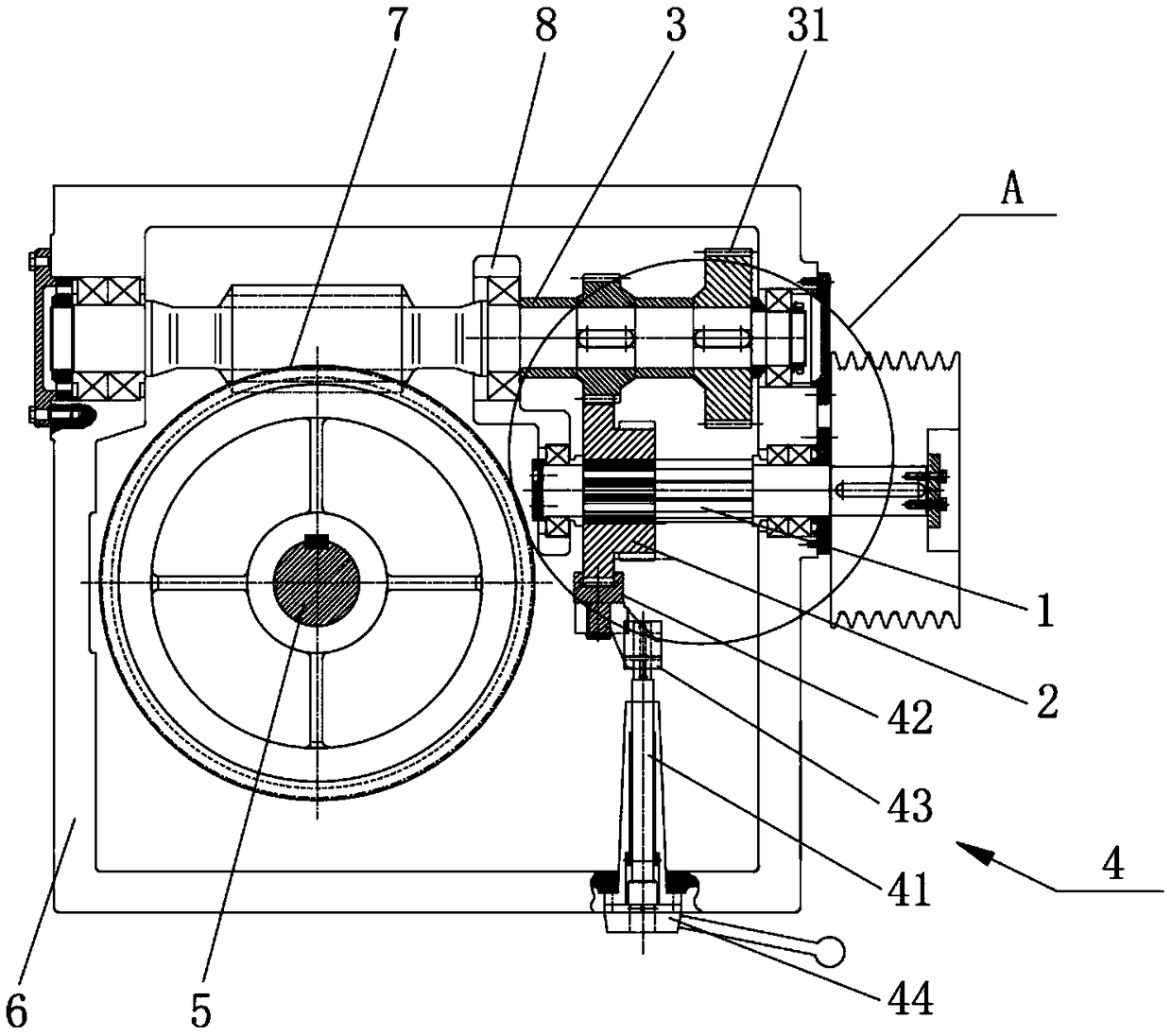
[0027] Such as figure 1 As shown, the present invention provides a multi-speed variable-speed drawing machine, including an input shaft 1, a multi-stage gear 2, a driven shaft 3, a driving member 4, an output shaft 5 and a casing 6, and the above-mentioned input shaft 1, driving member 4 And the output shaft 5 is rotatably installed on the box body 6 , and the above-mentioned multi-stage gear 2 and the driven shaft 3 are placed inside the box body 6 .

[0028] The above-mentioned input shaft 1 and the box body 6 are rotationally connected by bearings, which are used to connect with the motor, and the motor can drive the input shaft 1 to rotate. Specifically, the motor and the input shaft 1 can be connected by means of belts and pulleys.

[0029] The above-mentioned multi-stage gear 2 can rotate with the input...


PUM


Abstract

The invention belongs to the field of steel bar drawing equipment, and discloses a multi-gear variable speed drawing machine. The multi-gear variable speed drawing machine comprises an input shaft, amulti-stage gear, a driven shaft, a driving piece and an output shaft, wherein the multi-stage gear rotates along with the input shaft, can move in the axial direction of the input shaft, and is provided with at least two driving gears which rotate synchronously and are different in diameter; the driven shaft is fixedly provided with driven gears, and the driven gears and the driving gears are arranged in pairs; one end of the driving piece is connected to the multi-stage gear, and the driving piece is used for driving the multi-stage gear to move axially and be engaged with one of the drivengears; and the output shaft is in driving connection with a driven shaft and is driven by the driven shaft to rotate. Through the structure, drawing of steel bars different in diameter can be achieved, when the steel bars with different diameters are drawn, the multi-stage gear is driven to axially move through the driving piece, the driven gears and the driven gears which correspond to the steelbars with the diameter are engaged, large drawing force for the large-diameter steel bars and the high drawing speed of the small-diameter steel bars are achieved, and the motor power is sufficientlyutilized.

Description

technical field [0001] The invention relates to the field of steel bar drawing equipment, in particular to a multi-speed variable-speed drawing machine. Background technique [0002] Power is needed for steel bar rolling or drawing, and the drawing machine provides the power to pull the steel bar out of various abrasive tools. Usually, the motor drives the drawing machine, and then the drawing machine pulls the steel bar. At present, the drawing machines on the market have self-made gearboxes and direct-connected reducers to achieve power output. The above-mentioned methods all have only one reduction ratio. In the case of a wide range of steel bar diameters, there is only one structure with a reduction ratio. , the motor power will be greatly wasted. If the drawing machine can draw large-diameter steel bars, its power will inevitably be wasted when drawing small-diameter steel bars. [0003] Therefore be badly in need of a kind of steel bar that can pull large diameter, an...

Claims


Application Information

Patent Timeline
Patent Type & Authority Applications(China)
IPC IPC(8): F16H57/039F16H3/087
CPCF16H57/039F16H3/087
Inventor 陈振东
Owner TJK MACHINERY TIANJIN
Why Eureka
Try Eureka