Conduction oil heat exchanger
A technology of heat exchanger and heat transfer oil, which is applied in the types of heat exchangers, indirect heat exchangers, heat exchange equipment, etc. It can solve the problems of inconvenient transfer and achieve the effects of convenient movement, safe combustion, and convenient installation and fixation
- Summary
- Abstract
- Description
- Claims
- Application Information
AI Technical Summary
Problems solved by technology
Method used
Image

Examples
Embodiment Construction
[0018] The following will clearly and completely describe the technical solutions in the embodiments of the present invention with reference to the accompanying drawings in the embodiments of the present invention. Obviously, the described embodiments are only some, not all, embodiments of the present invention.
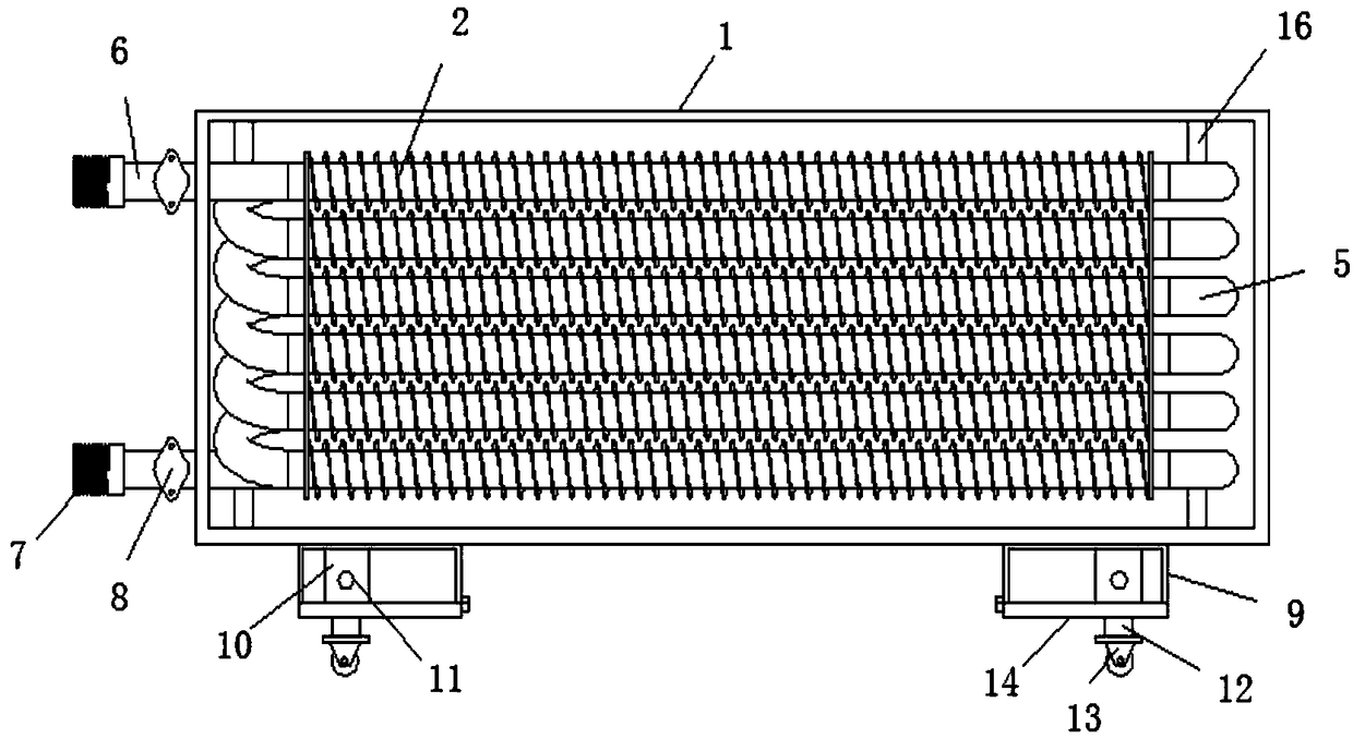
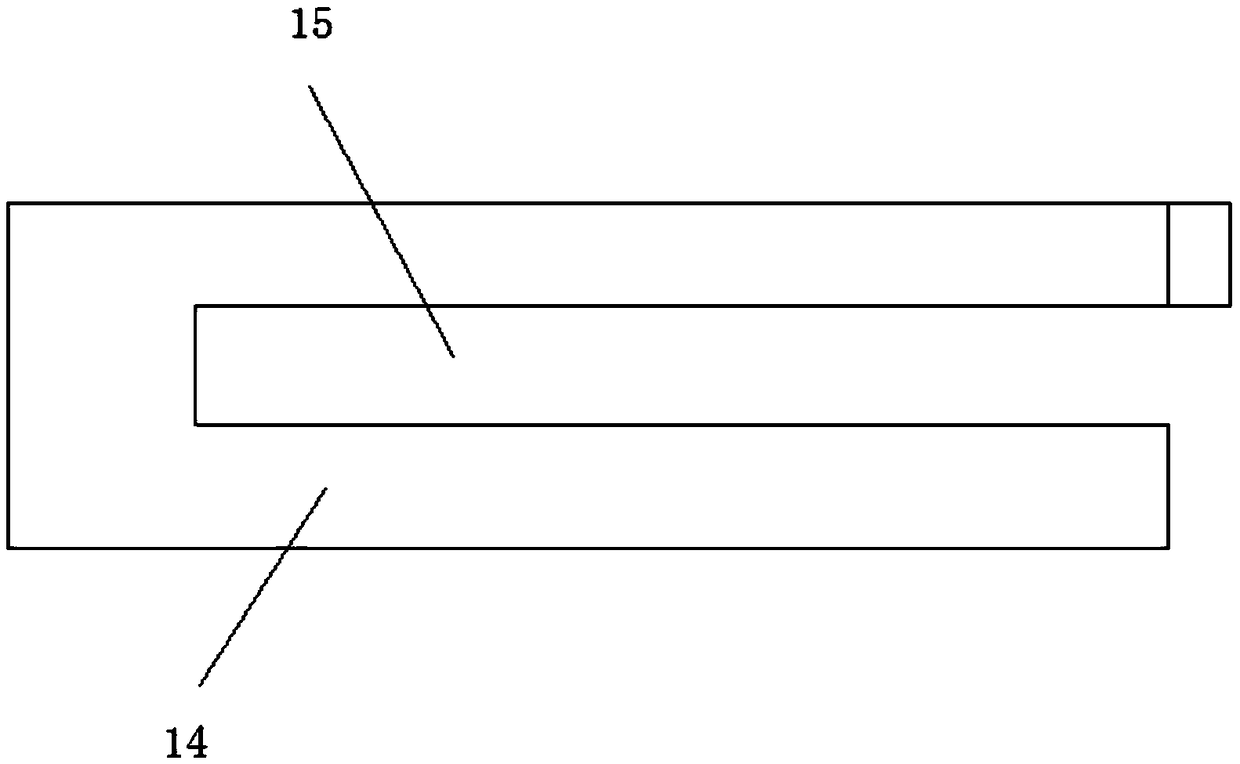
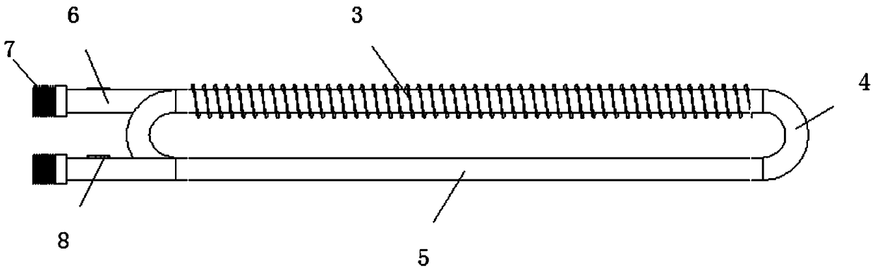
[0019] refer to Figure 1-3 , heat transfer oil heat exchanger, including a box body 1, the inside of the box body 1 is provided with a surrounding heat exchange tube group 2, and the heat exchange tube group 2 includes finned tubes 3, connecting tubes 4, and high-efficiency tubes 5 connected end to end in sequence , both ends of the heat exchange tube group 2 are connected with a fixed tube 6 fixedly socketed with the side wall of the box body 1, and the end of the fixed tube 6 extending out of the box body 1 is welded with a connector 7, and the fixed tube 6 extends out of the box The top of one end of the body 1 is welded with a fixed plate 8, the top inner wall a...
PUM
| Property | Measurement | Unit |
|---|---|---|
| Wall thickness | aaaaa | aaaaa |
| Outer diameter | aaaaa | aaaaa |
Abstract
Description
Claims
Application Information
 - R&D
- Intellectual Property
- Life Sciences
- Materials
- Tech Scout
- Unparalleled Data Quality
- Higher Quality Content
- 60% Fewer Hallucinations
Browse by: Latest US Patents, China's latest patents, Technical Efficacy Thesaurus, Application Domain, Technology Topic, Popular Technical Reports.
© 2025 PatSnap. All rights reserved.Legal|Privacy policy|Modern Slavery Act Transparency Statement|Sitemap|About US| Contact US: help@patsnap.com