Measuring method and system for five- and six-degree-of-freedom errors of shafting based on circular gratings

An error measurement and circular grating technology, which is applied in the field of shafting five- and six-degree-of-freedom error measurement and measurement systems based on circular gratings, can solve the problems of nonlinear time drift of sensors, few long-term application in production sites, and low measurement accuracy.

Active Publication Date: 2020-11-13
HENAN UNIV OF SCI & TECH
View PDF9 Cites 0 Cited by
  • Summary
  • Abstract
  • Description
  • Claims
  • Application Information

AI Technical Summary

Problems solved by technology

These sensors have relatively serious problems of nonlinearity, time drift, and temperature drift, and they need to be calibrated before they can be used. When the number of sensors is large, performance matching is required, and system debugging is difficult. Therefore, most of them are used in laboratory conditions. Under the research analysis, it is rarely used in the production site for a long time
In addition, the existing method of testing the rotation error of the measured shaft usually requires installing a standard ball at the end of the shaft as the measured reference, and then arranging multiple linear displacement sensors around it to form a measurement system. The accuracy of the installation position of the linear displacement sensor directly affects the measurement Therefore, the structure of the measurement system is complex and requires high test conditions. It is difficult to integrate at low cost into the mass-produced instrument products to realize the online measurement and compensation of the shaft rotation error. The most important thing is the roundness error of the side It will directly affect the measurement results of the product, and the measurement accuracy is low

Method used


Image

  • Measuring method and system for five- and six-degree-of-freedom errors of shafting based on circular gratings
  • Measuring method and system for five- and six-degree-of-freedom errors of shafting based on circular gratings
  • Measuring method and system for five- and six-degree-of-freedom errors of shafting based on circular gratings

Examples


Embodiment Construction

[0058] Embodiments of the present invention will be further described below in conjunction with the accompanying drawings.

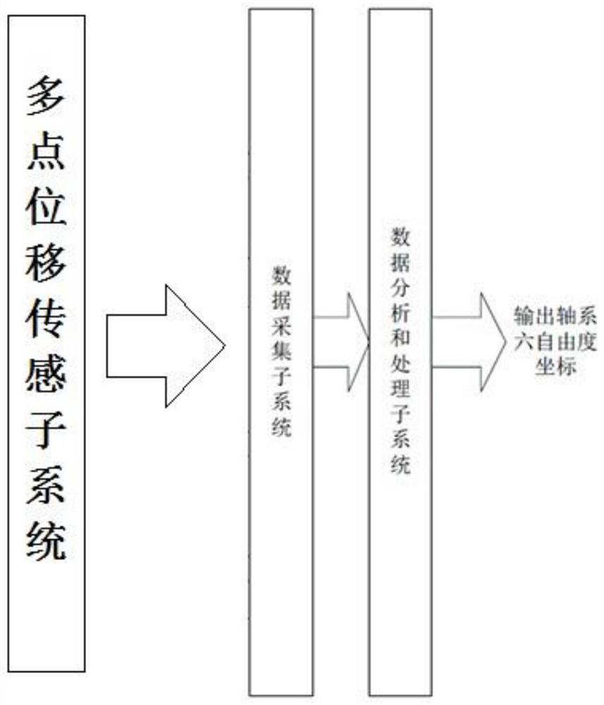
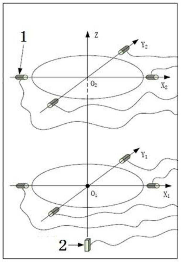
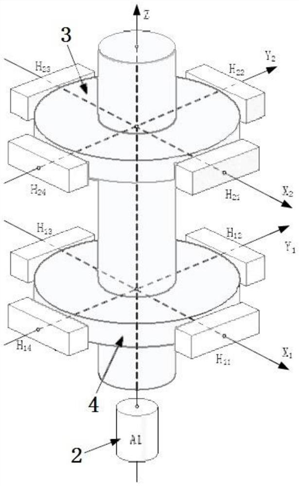
[0059] The specific embodiment of the method for measuring the six degrees of freedom error of the shaft system based on the circular grating of the present invention is as follows: Figure 1 to Figure 7 As shown, the measurement system uses the circular grating that has been widely used in the industrial field as the main sensor device, and the circular grating read head as the tangential displacement sensor to establish a high-precision, high-reliability, and strong environmental adaptability shaft error The measurement system realizes the measurement of the shafting error. The measurement method obtains the coordinates of the six-degree-of-freedom movement of the shaft system by analyzing and processing the readings of each sensor.

[0060] Such as figure 1 As shown, the measurement system is composed of three parts: (1) multi-point displacement sen...


PUM


Abstract

The invention relates to a circular grating-based shaft system five-degree-of-freedom error measurement method, a circular grating-based shaft system six-degree-of-freedom error measurement method anda measurement system. According to the measurement methods and measurement system, two or more measuring planes are arranged at intervals on the axial position of the measured shaft of a shaft system; circular gratings are disposed at positions on the measured shaft which are corresponding to each of the measuring planes respectively; each measuring plane is provided with a reading head corresponding to the corresponding circular grating; if the axis of the measured shaft moves, the tangential displacement of the measured shaft changes when the measured shaft rotates in the measuring planes,and therefore, the plane displacement of the measured shaft on the detecting planes can be generated; and since the displacement is a relative variable relative to the initial position of the measuredshaft, the displacement is not affected by the roundness of the measured shaft itself.

Description

technical field [0001] The invention relates to a method and system for measuring errors of five and six degrees of freedom of a shaft system based on a circular grating. Background technique [0002] The precision rotary shaft system is used in many precision machinery, such as the measured axis of the tool or the workpiece of the precision machine tool, the measured axis of the turntable of the gear measurement center, the measured axis of the worm of the gear overall error measuring instrument, and the measured axis of the gear. The shaft and the measured shaft of the workpiece of the roundness meter belong to the precision rotary shaft system. [0003] The ideal shaft system has no error, and the measured shaft has no other degrees of freedom except rotation during work. However, the actual axis system has errors, and the measured axis will have error motion along each degree of freedom during rotation. In the precision rotary shaft system, the motion of the measured s...

Claims


Application Information

Patent Timeline
Patent Type & Authority Patents(China)
IPC IPC(8): G01B11/00G01B11/02G01B11/26
CPCG01B11/00G01B11/02G01B11/26
Inventor 王笑一张书涛张波
Owner HENAN UNIV OF SCI & TECH
Why Eureka
Try Eureka