Method for detecting insertion depth of connecting steel bar in semi-grouting sleeve steel bar joint

A semi-grouting sleeve and connecting steel bar technology, which is applied in the direction of measuring devices, instruments, optical devices, etc., can solve the problem that the joint strength of the steel bar sleeve grouting connection cannot meet the requirements, the connecting steel bar in the lower section is cut short or cut off, and the effectiveness of reducing the steel bar is solved. Anchorage length and other issues, to facilitate the calculation of the insertion depth of the connecting steel bar, improve the detection accuracy, and accurately calculate the insertion depth of the connecting steel bar

Active Publication Date: 2019-01-04
KUNSHAN CONSTRUCT ENG QUALITY TESTING CENT
View PDF6 Cites 10 Cited by
  • Summary
  • Abstract
  • Description
  • Claims
  • Application Information

AI Technical Summary

Problems solved by technology

However, due to component production or on-site installation deviations, the lower connecting steel bars cannot be placed in place, and some of the lower connecting steel bars are cut short or cut off, which reduces the effective anchorage length of the steel bars, resulting in the strength of the steel sleeve grouting connection joints failing to meet the requirements. There are security risks

Method used


Image

  • Method for detecting insertion depth of connecting steel bar in semi-grouting sleeve steel bar joint
  • Method for detecting insertion depth of connecting steel bar in semi-grouting sleeve steel bar joint
  • Method for detecting insertion depth of connecting steel bar in semi-grouting sleeve steel bar joint

Examples


Embodiment Construction

[0035] The present invention will be further described below in conjunction with the accompanying drawings and specific embodiments, so that those skilled in the art can better understand the present invention and implement it, but the examples given are not intended to limit the present invention.

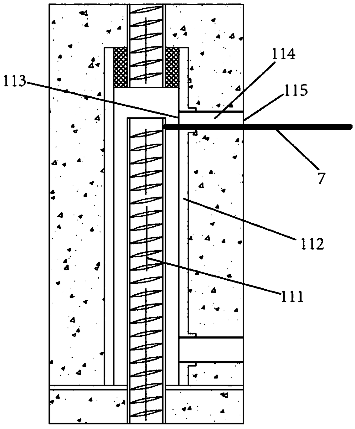
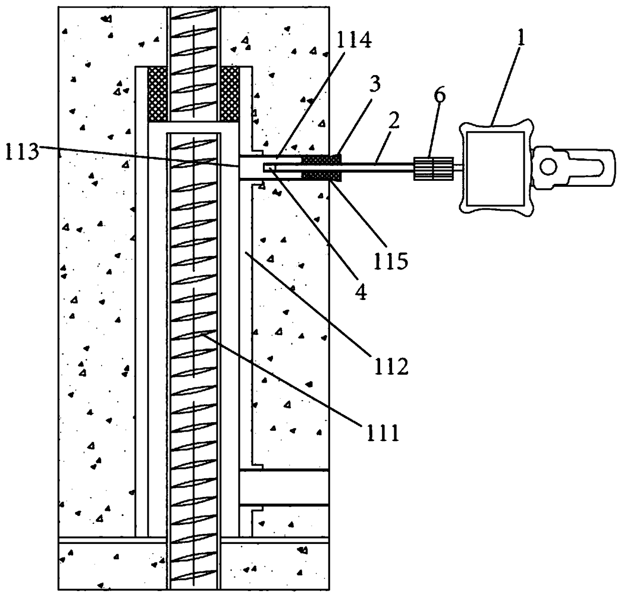
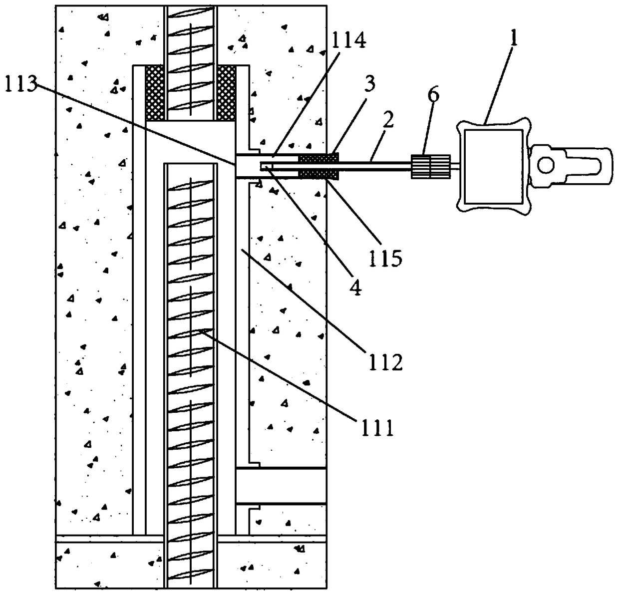
[0036] In order to solve the above-mentioned technical problems, the present invention provides a method for detecting the insertion depth of the connecting steel bar in the semi-grouting sleeve steel bar joint. Before the detection, a three-dimensional measuring endoscope 1, a rigid sleeve 2 and a rubber plug 3 are prepared; wherein , the three-dimensional measurement endoscope includes the endoscope host connected in sequence, the connecting hose, the probe and the lens, and the lens includes the front-view three-dimensional measurement lens 4 and the side-view three-dimensional measurement lens 5; one end of the rigid sleeve is provided with a rigid sleeve Pipe handle 6, easy to...


PUM


Abstract

The invention discloses a method for detecting the insertion depth of a connecting steel bar in a semi-grouting sleeve steel bar joint. A three-dimensional measurement endoscope, a rigid sleeve pipe and a rubber plug. The three-dimensional measurement endoscope comprises an endoscope host, a connection hose, a probe and lenses connected in sequence, and the lenses comprise a front-view three-dimensional measuring lens and a side-view three-dimensional measuring lens. A central hole is arranged in the middle of the rubber plug, and the rigid sleeve can be inserted into the rubber plug through the central hole. The relative position of an end of an inserted section of the connecting steel bar and the bottom of a sleeve grout discharging port is judged by using an auxiliary tool. When a judgment result is that the end of the inserted section of the connecting steel bar is above the bottom of the sleeve grout discharging port, the front-view three-dimensional measuring lens is used to measure and calculate to obtain a result, and when the judgment result is that the end of the inserted section of the connecting steel bar is under the bottom of the sleeve grout discharging port, the side-view three-dimensional measuring lens is used to measure and calculate to obtain a result. According to the method, the insertion depth of the steel bar can be intuitively, clearly and quantitatively obtained, and the detection efficiency is improved.

Description

technical field [0001] The invention relates to the field of prefabricated buildings, in particular to a method for detecting the insertion depth of a connecting steel bar in a semi-grouting sleeve steel bar joint. Background technique [0002] As a structural form in line with industrial production methods, prefabricated concrete structures have the advantages of fast construction speed, low labor intensity, less noise pollution and wet work, and easy control of product quality. It has become the mainstream development direction of the construction industry at home and abroad. [0003] In prefabricated building structures, especially in prefabricated concrete structures, component connection is a key node to ensure the overall quality of the structure. Rebar sleeve grouting connection is a common form of rebar connection in prefabricated concrete structures. It refers to the rebar butt joint connection method realized by inserting rebar into the pre-embedded metal sleeve in...

Claims


Application Information

Patent Timeline
Patent Type & Authority Applications(China)
IPC IPC(8): G01B11/22
CPCG01B11/22
Inventor 顾盛常儇宇吴玉龙刘以龙蒋向于陈淞
Owner KUNSHAN CONSTRUCT ENG QUALITY TESTING CENT
Why Eureka
Try Eureka