
Tailstock control device

a control device and tailstock technology, applied in the direction of program control, electric programme control, instruments, etc., can solve the problems of inability to support the workpiece, inability to achieve stable support thrust, and excessively large workpiece support zones, so as to achieve short acceleration time and reduce the distance between drive torque and torqu

Active Publication Date: 2017-04-04
OKUMA CORP
View PDF5 Cites 0 Cited by
  • Summary
  • Abstract
  • Description
  • Claims
  • Application Information

AI Technical Summary

Benefits of technology

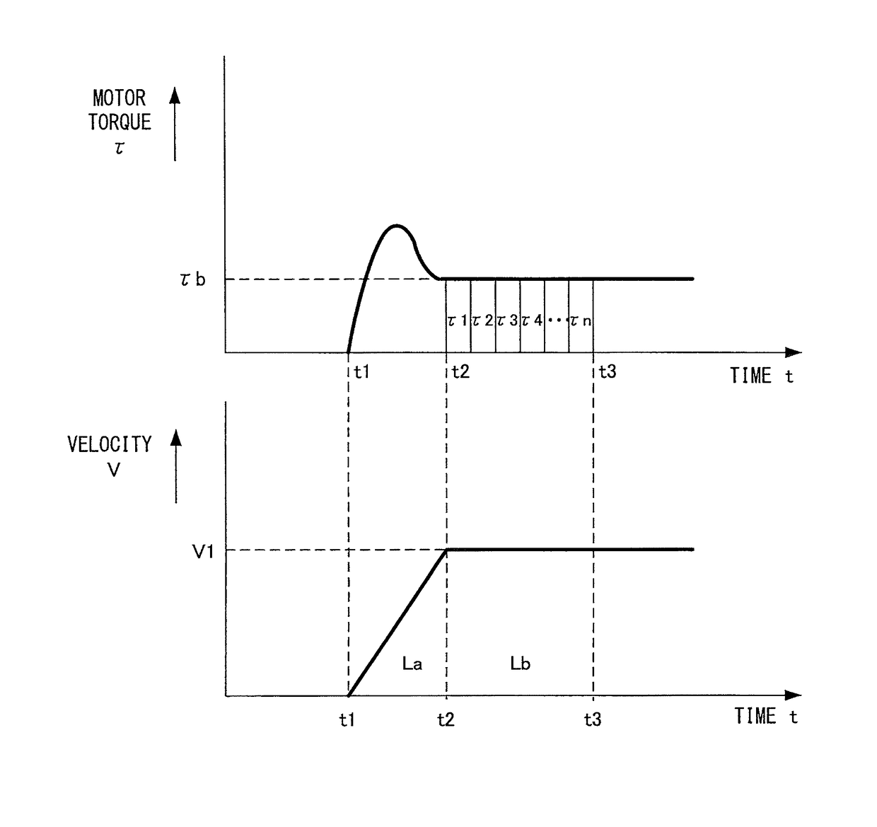
The present invention relates to a system for measuring the torque applied to a machine's workpiece during a machining process. The system uses a servo motor to control the movement of the workpiece during the process. The distance between the tailstock and the workpiece during acceleration and constant velocity phases of the movement is measured and used to calculate the movement distance. By dividing the measurement distance into two phases, the system can optimize the measurement process and minimize the distance between the workpiece and the tailstock, which improves the overall efficiency of the machining process.

Problems solved by technology

In supporting a workpiece with an electrically-driven tailstock, there exists a problem that, by simply driving and controlling the servo motor to obtain a tailstock support thrust by a drive torque supplied in consideration of the gear ratio of the drive system, a stable support thrust cannot be obtained, due to the transmission efficiency of the transmission mechanism of the drive system.
For this reason, in this zone, it is not possible to support the workpiece.
However, the preset drive torque measuring distance is a uniform distance for all cases regardless of the servo characteristics, and is set at a distance longer than that actually required for the drive torque measurement, so that, disadvantageously, the zone in which a workpiece cannot be supported is excessively large.

Method used


Image

  • Tailstock control device
  • Tailstock control device
  • Tailstock control device

Examples


Embodiment Construction

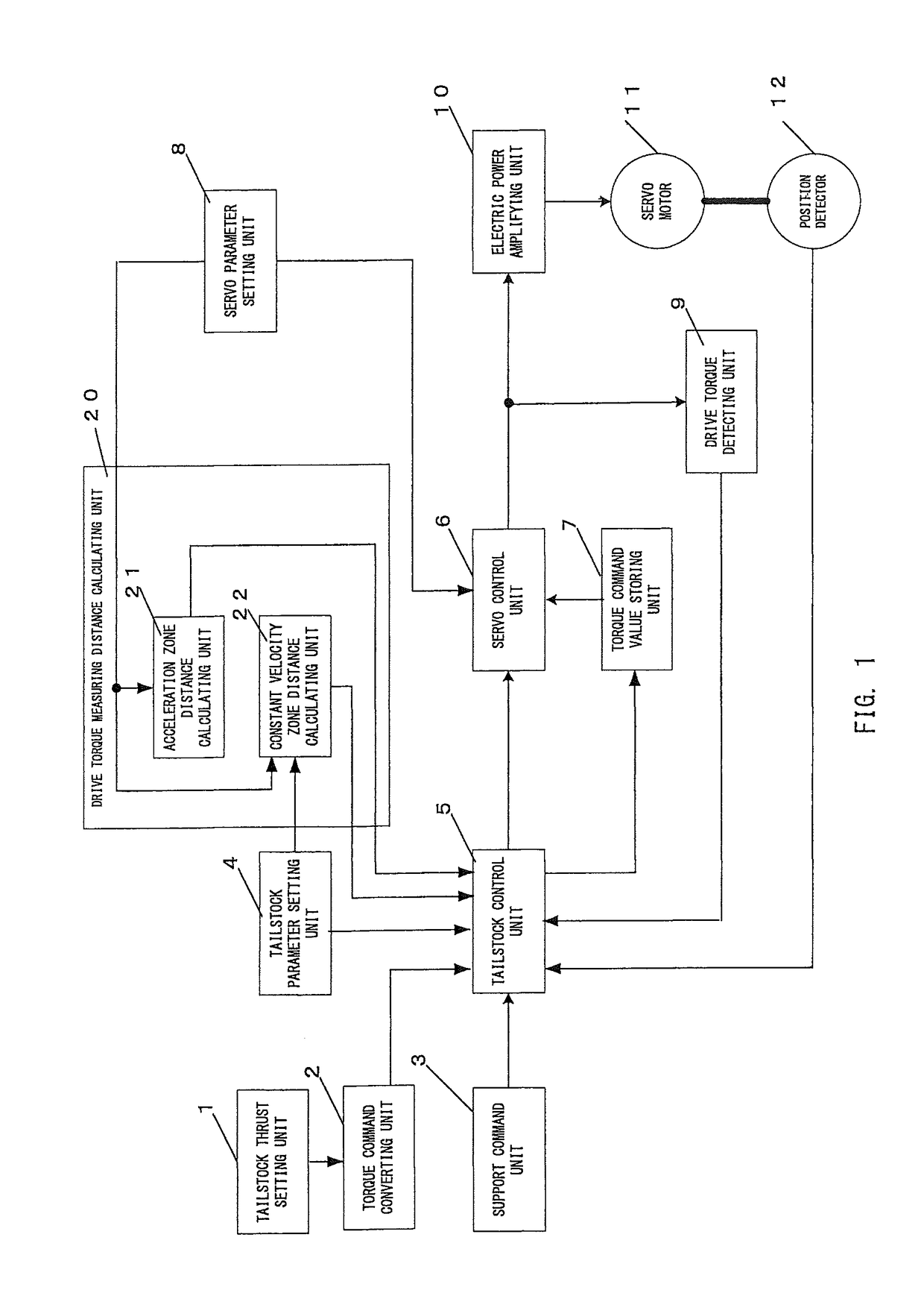
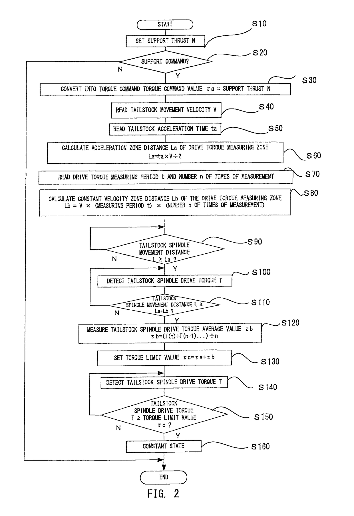
[0014]An embodiment of the present invention is described below with reference to the block diagram in FIG. 1 and the flowchart illustrating a tailstock control in FIG. 2. Concerning matters equivalent to those in the conventional art, detailed description is omitted.

[0015]A servo parameter setting unit 8 receives, in advance, setting of a tailstock movement velocity V, a tailstock acceleration time ta, a drive torque measuring period t, and a number n of times of drive torque measurement. Further, prior to performing a support control, a tailstock thrust setting unit 1 receives, in advance, setting of a tailstock thrust N for supporting a workpiece (step S10). Subsequently, when a support command is given by a manual operation or a machining program (not shown), a tailstock control unit 5 is activated via a support command unit 3 (step S20). In order to support a workpiece with a predetermined support thrust, the activated tailstock control unit 5 causes a torque command converting...


PUM


Abstract

A tailstock control device includes a tailstock parameter setting unit that receives, in advance, setting of tailstock acceleration time ta, tailstock movement velocity V, drive torque measuring period t, and number n of drive torque measurements; a calculating unit that calculates acceleration zone distance La from the acceleration time ta and the movement velocity V; a calculating unit that calculates constant velocity zone distance Lb from the movement velocity V, the measuring period t, and the number n of measurements; a drive torque detecting unit that detects servo motor drive torque; and a control unit that sets La+Lb as drive torque measuring distance Lt and calculates servo motor drive torque limit value τc from drive torque T detected by the drive torque detecting unit when the tailstock is moved over La+Lb and also from a servo motor torque command value τa required for supporting a workpiece.

Description

CROSS REFERENCE TO RELATED APPLICATIONS[0001]The present invention claims priority under 35 U.S.C. §119 to Japanese Application No. 2014-091859, filed on Apr. 25, 2014, the entire content of which is incorporated herein by referenceFIELD OF THE INVENTION[0002]The present invention relates to a tailstock control device that controls drive of a tailstock which supports a workpiece using a tailstock center.BACKGROUND OF THE INVENTION[0003]In a numerically-controlled lathe, a tailstock for supporting a workpiece had in the past often been driven hydraulically, but in recent years, an electrically-driven tailstock driven and controlled by a servo motor has been employed. An electrically-driven tailstock supports a workpiece by pushing, against a center hole of the workpiece, a tailstock center mounted on the tailstock driven by a feed screw coupled to a servo motor. In supporting a workpiece with an electrically-driven tailstock, there exists a problem that, by simply driving and control...

Claims


Application Information

Patent Timeline
Patent Type & Authority Patents(United States)
IPC IPC(8): B23Q15/20B23B23/00G05B19/416B23Q15/12B23Q17/00
CPCB23B23/00G05B19/4166B23Q15/12B23Q15/20B23Q17/002B23Q17/005G05B2219/37589G05B2219/42176Y10T82/2502
Inventor ICHIKAWA, YOSHIICHI
Owner OKUMA CORP
Learn More