
Engine test stand

A technology of engine and test bench, applied in the field of test and measurement, can solve the problems of high cost, no mature technology, long test period, etc., and achieve the effect of simple structure and high simulation accuracy

Pending Publication Date: 2019-01-04
BEIJING AEROSPACE SANFA HIGH TECH
View PDF0 Cites 2 Cited by
  • Summary
  • Abstract
  • Description
  • Claims
  • Application Information

AI Technical Summary

Problems solved by technology

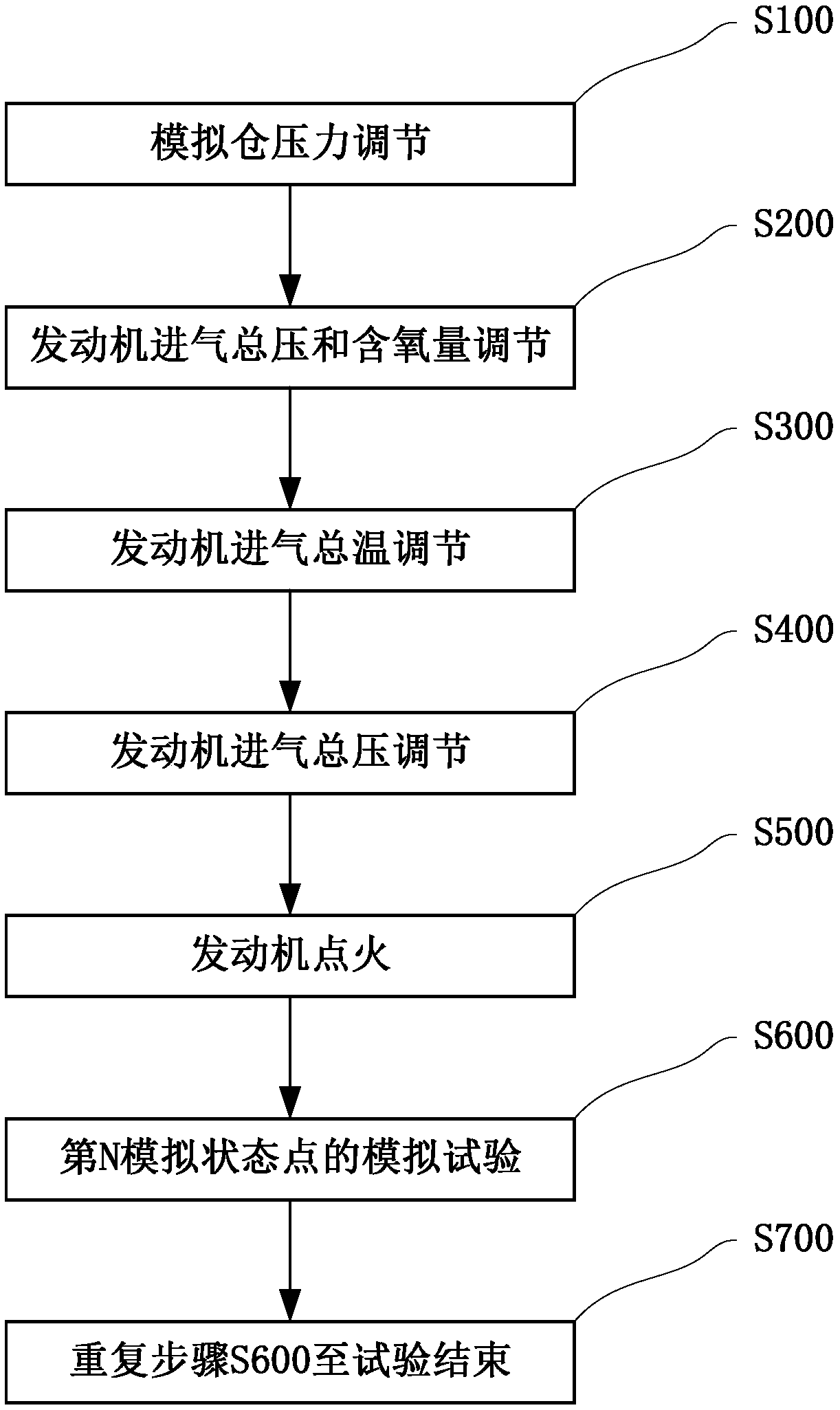
[0002] Before the test flight of the aero-engine, a high-altitude simulation test needs to be done on the ground. During the engine test, a set of parameters are required, including the total intake pressure, the intake air flow rate, the intake oxygen content, the total intake temperature, and the amount of fuel supplied to the engine. , the air environment pressure is called the state point. After reaching the set value and being stable at the same time, record its performance and parameters or evaluate its performance. The existing engine test bench technology is not yet mature for engine intake simulation and flight environment pressure simulation. At the same time, there is no accurate theoretical method for judging when the simulation state reaches a stable state, resulting in poor test simulation effect, long test period, high cost, and serious waste of resources

Method used


Image

  • Engine test stand
  • Engine test stand
  • Engine test stand

Examples


Embodiment Construction

[0018] In describing the present invention, it should be understood that the terms "center", "longitudinal", "transverse", "length", "width", "thickness", "upper", "lower", "front", " Back", "Left", "Right", "Vertical", "Horizontal", "Top", "Bottom", "Inner", "Outer", "Clockwise", "Counterclockwise", "Axial", The orientation or positional relationship indicated by "radial", "circumferential", etc. is based on the orientation or positional relationship shown in the drawings, and is only for the convenience of describing the present invention and simplifying the description, rather than indicating or implying the referred device or element Must be in a particular orientation, be constructed in a particular orientation, and operate in a particular orientation, and therefore should not be construed as limiting the invention. In addition, the features defined as "first" and "second" may explicitly or implicitly include one or more of these features. In the description of the prese...


PUM


Abstract

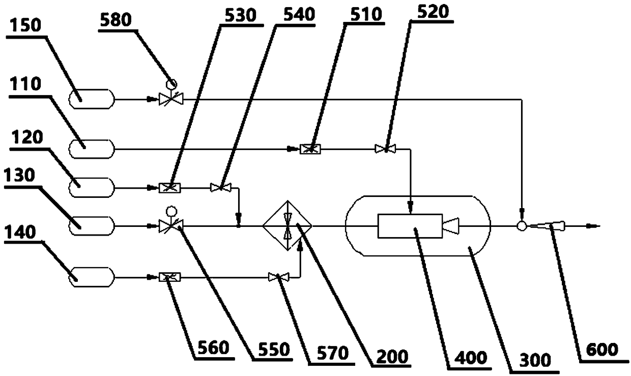
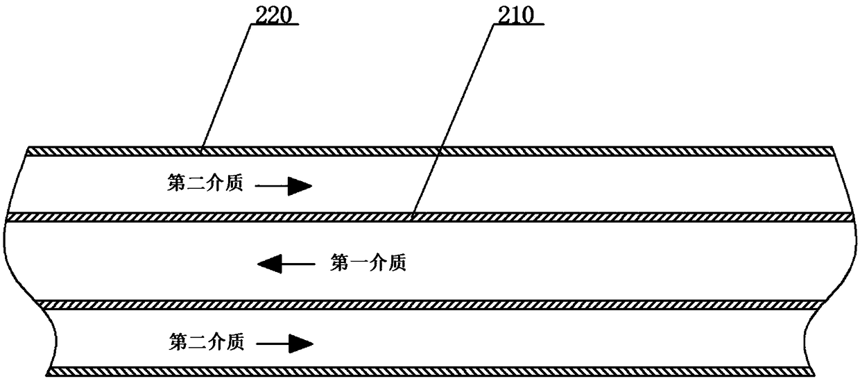
The invention relates to an engine test stand, which comprises a supply source, a temperature simulation unit, a simulation chamber and an exhaust ejector, wherein the supply source includes a fuel supply source, an oxygen supply source, an engine intake air supply source, an alcohol supply source and an ejector active air flow supply source; the temperature simulation unit includes a pipe body and a shell, the pipe body is located inside the shell and internally provided with a first medium channel, the space between the outer wall of the pipe body and the inner wall of the shell forms a second medium channel; the tested engine is located in the simulation chamber; the fuel oil supply source is communicated with the tested engine through a pipeline, the oxygen supply source and the engineintake air supply source are communicated with an inlet of the second medium channel through pipelines, an outlet of the second medium channel is communicated with an air inlet of the tested engine through a pipeline, the alcohol supply source passes through an igniter and then is communicated with an inlet of the first medium channel through a pipeline, the ejector active air flow supply sourceis communicated with the exhaust ejector through a pipeline, and the exhaust ejector passes through the simulation chamber and is close to an exhaust pipe of the tested engine.

Description

technical field [0001] The invention relates to the technical field of test and measurement, in particular to an engine test bench. Background technique [0002] Before the test flight of the aero-engine, a high-altitude simulation test needs to be done on the ground. During the engine test, a set of parameters are required, including the total intake pressure, the intake air flow rate, the intake oxygen content, the total intake temperature, and the amount of fuel supplied to the engine. , the air environment pressure is called the state point. After reaching the set value and being stable at the same time, record its performance and parameters or evaluate its performance. The existing engine test bench technology is not yet mature for engine intake simulation and flight environment pressure simulation. At the same time, there is no accurate theoretical method for judging when the simulation state reaches a stable state, resulting in poor test simulation results, long test ...

Claims


Application Information

Patent Timeline
Patent Type & Authority Applications(China)
IPC IPC(8): G01M15/14G01M15/02
CPCG01M15/02G01M15/14
Inventor 王文彬康宏博李强徐元元
Owner BEIJING AEROSPACE SANFA HIGH TECH
Learn More