An atomization system for electrolytic copper foil penetration point and pinhole detection and its application

An atomization system and electrolytic copper foil technology, which is applied in the field of electrolytic copper foil, can solve the problems such as the inability to detect copper foil

Inactive Publication Date: 2020-12-15
苏州绣创投资发展有限公司
View PDF8 Cites 0 Cited by
  • Summary
  • Abstract
  • Description
  • Claims
  • Application Information

AI Technical Summary

Problems solved by technology

However, the above method needs to cut the copper foil and cannot detect the entire copper foil

Method used


Image

  • An atomization system for electrolytic copper foil penetration point and pinhole detection and its application
  • An atomization system for electrolytic copper foil penetration point and pinhole detection and its application
  • An atomization system for electrolytic copper foil penetration point and pinhole detection and its application

Examples


Embodiment 1

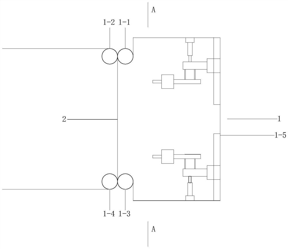
[0080] Embodiment 1: The detection equipment for the penetration point and pinhole of the electrolytic copper foil includes: an atomization system 1 and a copper foil 2 .

[0081] Atomization system 1 includes: atomization system frame, top guide roller 1-1, top drive roller 1-2, bottom guide roller 1-3, bottom drive roller 1-4, housing 1-5; top guide roller 1- 1. The top drive roller 1-2, the bottom guide roller 1-3, the bottom drive roller 1-4, and the housing 1-5 are all fixed on the frame of the atomization system;

[0082] The top guide roller 1-1, the top drive roller 1-2, the bottom guide roller 1-3, and the bottom drive roller 1-4 are arranged horizontally;

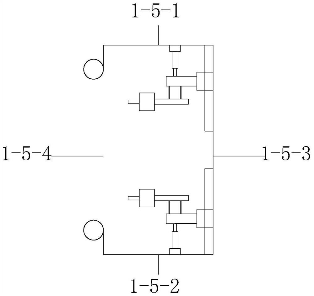
[0083] The shell includes: an upper plate 1-5-1, a lower plate 1-5-2, and a side wall plate 1-5-3, and an opening 1-5-4 is arranged on the side wall plate; the shell can be a cuboid or cylinder;

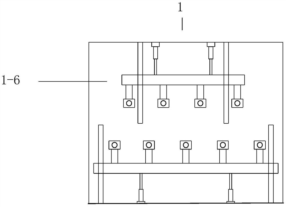
[0084] Also includes: the first mobile spray system 1-6, the second mobile spray system 1-7, the first mobile spray ...

Embodiment 2

[0117] Embodiment two: the bottom guide roller 1-3, the bottom driving roller 1-4 in the embodiment one, the copper foil passes through the extrusion of both the bottom guiding roller 1-3 and the bottom driving roller 1-4, so that the dilute sulfuric acid solution is subjected to After squeezing, it can enter the penetration points and pinholes more fully.

[0118] However, the first embodiment has the following difference. When the equipment is running for a long time, more solution will accumulate at the bottom of the atomization system 1, especially at the bottom guide rollers 1-3 and bottom driving rollers 1-4. The purpose of the second embodiment is to solve the above problems.

[0119] The difference from Embodiment 1 is that: the bottom guide roller 1-3 and the bottom driving roller 1-4 are cancelled. The lower plate of the housing of the atomization system 1 is provided with an L-shaped plate body 1-8, and a third telescopic power mechanism 1-9 is fixed on the vertica...

Embodiment 3

[0122] Embodiment three: on the basis of embodiment two, further improvement. The bottom guide roller 1-3 and the bottom drive roller 1-4 are arranged under the housing 1-5, that is, the copper foil first passes through the rubber block 1-10 and the vertical support 3 to initially remove moisture, and then passes through the bottom guide roller 1- 3. The bottom drive rollers 1-4 make the copper foil run from vertical to horizontal, so that dilute sulfuric acid solution can enter the penetration point and pinhole; finally, the fourth telescopic power is installed on the lower surface of the lower plate of the shell mechanism, the other end of the fourth telescopic power mechanism is connected with a pressing plate, and the surface of the pressing plate is provided with a plurality of pressing rubber blocks at intervals, and the width of the rubber blocks is the same as that of the copper foil.

[0123] The method of embodiment 3 is that after the copper foil is sprayed, the sol...


PUM


Abstract

The invention relates to an atomizing system for electrolytic copper foil penetration point and pinhole detection and an application of the atomizing system. The atomizing system is characterized in that a fourth telescopic power mechanism is mounted on the lower surface of the lower portion of a shell, the other end of the fourth telescopic power mechanism is connected with a clamping plate, a plurality of clamping rubber blocks are arranged on the surface of the clamping plate at intervals, and the width of each rubber block is as same as that of a copper foil. By the aid of the atomizing system for electrolytic copper foil penetration point and pinhole detection and the application of the atomizing system, whole dilute sulfuric acid can be automatically applied in copper foil penetration point and pinhole detection.

Description

technical field [0001] The invention relates to the technical field of electrolytic copper foil, in particular to an atomization system for detection of penetration points and pinholes of electrolytic copper foil and its application. Background technique [0002] CN102798638A discloses a method for detecting penetration points and pinholes of electrolytic copper foil, which includes the following steps: (1), sample processing: select a wide water tank as the detection water tank, and trim the copper foil to be tested into one without wrinkles and creases. For the sample, the size of the sample is required to be placed flat in the detection tank; (2), prepare the penetrant: dissolve the dye in alcohol at a concentration of 0.5g / L-5g / L, and fill it into the detection tank; (3) Rough inspection: take the sample and put it into a test tank filled with permeate liquid facing down, leave it for 0.5 minutes to 2 minutes, observe the color points of the permeated rough surface to ju...

Claims


Application Information

Patent Timeline
Patent Type & Authority Patents(China)
IPC IPC(8): G01N21/91G01N21/01B05B3/04B05B13/02B05B14/00
CPCB05B3/04B05B13/0278B05B14/00G01N21/01G01N21/91G01N2021/0112
Inventor 赵玮
Owner 苏州绣创投资发展有限公司
Why Eureka
Try Eureka