
Common scattering angle gather-based scattering wave separation method

A technique of separation method and scattering angle, which is applied in the field of seismic migration imaging in the field of geophysical exploration and seismic data processing, and can solve the problems of imperfect separation and imaging of scattered waves

Active Publication Date: 2019-01-04
CHINA PETROLEUM & CHEM CORP +1
View PDF5 Cites 5 Cited by
  • Summary
  • Abstract
  • Description
  • Claims
  • Application Information

AI Technical Summary

Problems solved by technology

Generally speaking, the research on scattered wave separation imaging at home and abroad is still not perfect, and there is much room for research in both theory and application.

Method used


Image

  • Common scattering angle gather-based scattering wave separation method
  • Common scattering angle gather-based scattering wave separation method
  • Common scattering angle gather-based scattering wave separation method

Examples


Embodiment

[0125] In order to better understand the method of the present invention, an embodiment of the present invention is described with reference to the accompanying drawings.

[0126] Figure 8 It is a model designed to simulate karst cave geological phenomena, which includes scatterers of different scales with diameters of 10m, 20m, 30m, 40m and 50m. The speed is 2000m / s. The acquisition method of this model is to shoot in the middle, and a total of 151 shots are collected, the number of each shot is 601, the shot spacing is 40m, the receiver point distance is 10m, and the grid size is 10m both vertically and horizontally. The single-shot record of the ongoing performance is as follows: Figure 9 shown.

[0127] Figure 10 It is the effect comparison diagram before and after scattering wave separation, Figure 10 (a) is the full wave field profile, Figure 10 (b) is the scattered wave profile. It can be seen from the comparison that the reflection event is eliminated relati...


PUM


Abstract

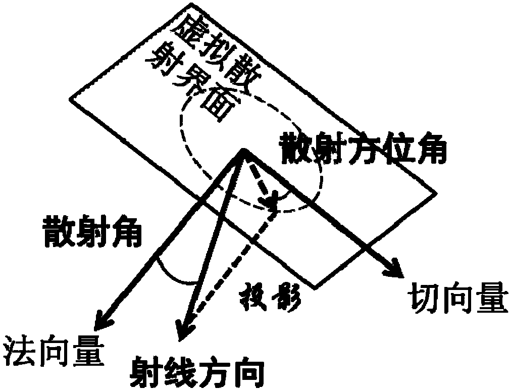
The invention discloses a common scattering angle gather-based scattering wave separation method. The method includes the following steps that: data are shifted to a scattering angle domain through common scattering angular shift, so that a common scattering angle gather can be generated; and reflected waves and scattered waves are separated from each other according to the different response features of the reflected waves and scattered waves in the common scattering angle gather. With the common scattering angle gather-based scattering wave separation method of the invention adopted, the scattered waves can be well preserved under a premise that the reflected waves are separated out, and therefore, a capacity for recognizing the scattered waves can be improved, and a capacity for distinguish a fracture-cavity reservoir can be enhanced.

Description

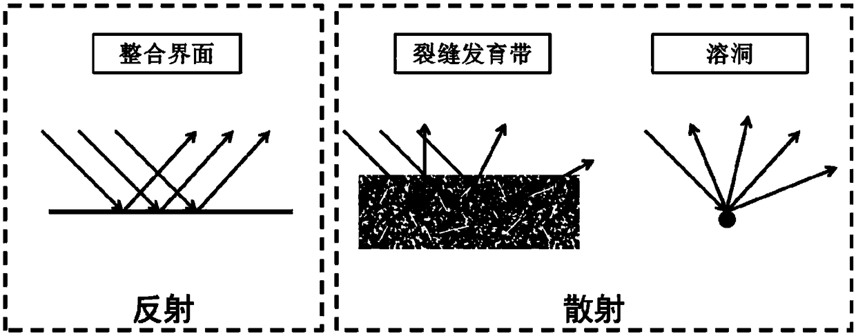
technical field [0001] The invention relates to the field of geophysical exploration, more specifically, to the field of seismic migration imaging in the field of seismic data processing, and to a scattered wave separation method based on common scattering angle gathers. Background technique [0002] Seismic scattered waves are always associated with small-scale geological phenomena. Small-scale fractures and caves in carbonate reservoirs are important oil and gas storage spaces. Using separate scattered waves for separate imaging is beneficial to the identification and analysis of such reservoirs. exploration. [0003] There are many difficulties in the study of scattered waves. Firstly, the propagation of scattered waves is different from that of reflected waves. It has no clear direction and shows strong divergence. Therefore, scattered waves have the following two characteristics. The other is that the energy is not concentrated, and it is often suppressed by other stro...

Claims


Application Information

Patent Timeline
Patent Type & Authority Applications(China)
IPC IPC(8): G01V1/34
CPCG01V1/345G01V2210/74
Inventor 白英哲
Owner CHINA PETROLEUM & CHEM CORP
Learn More