High-frequency power supply device and reflected wave power control method

Active Publication Date: 2015-03-26
KYOSAN ELECTRIC MFG CO LTD
View PDF1 Cites 66 Cited by
  • Summary
  • Abstract
  • Description
  • Claims
  • Application Information

AI Technical Summary

Benefits of technology

[0097]As described above, in an RF generator that supplies RF power to a plasma load through the pulse operation, the present invention realizes total reflected wave power tolerance, which is the ability to tolerate total reflected wave power generated when forward wave power all returns to the generator side as reflected wave power, in the non-ignition state before plasma is ignited.
[0098]In addition, the present invention prevents an incorrect determinat

Problems solved by technology

For example, an RF power amplifier device, which is one of the components of a class-D RF generator, may suffer thermal damage due to heat

Method used


Image

  • High-frequency power supply device and reflected wave power control method
  • High-frequency power supply device and reflected wave power control method
  • High-frequency power supply device and reflected wave power control method

Examples


Embodiment Construction

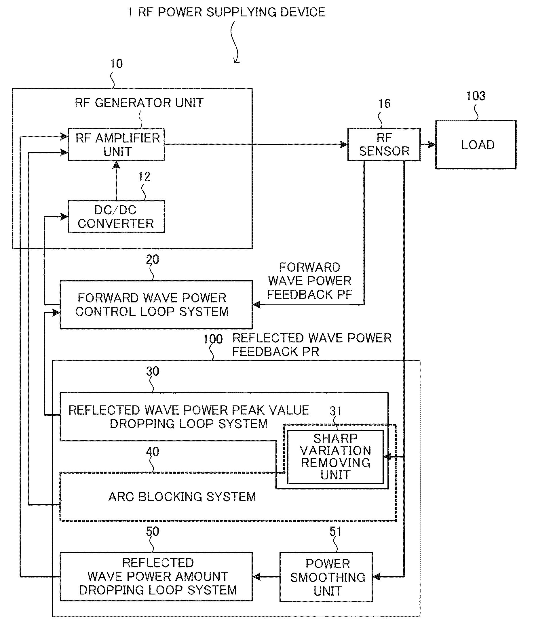
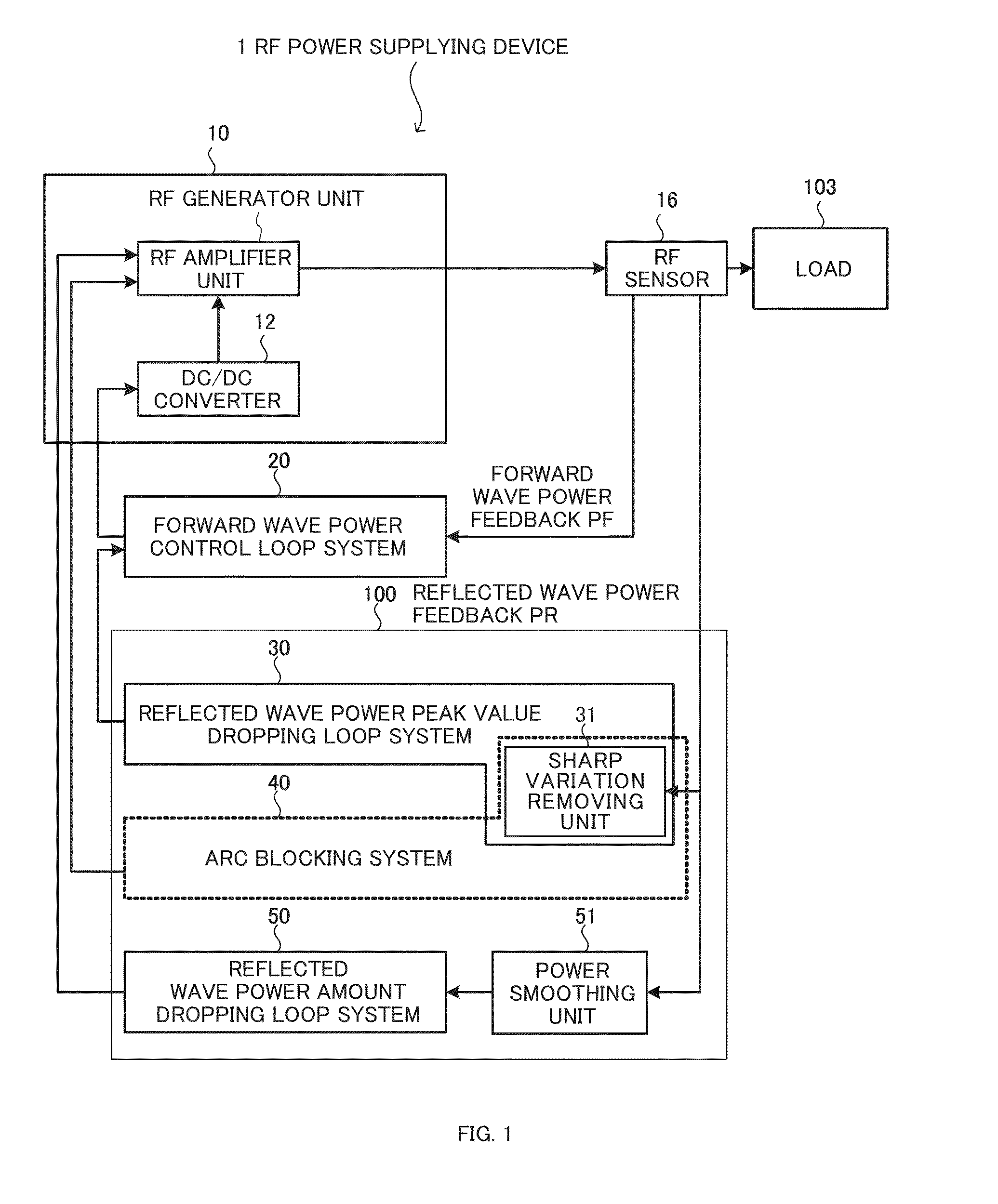
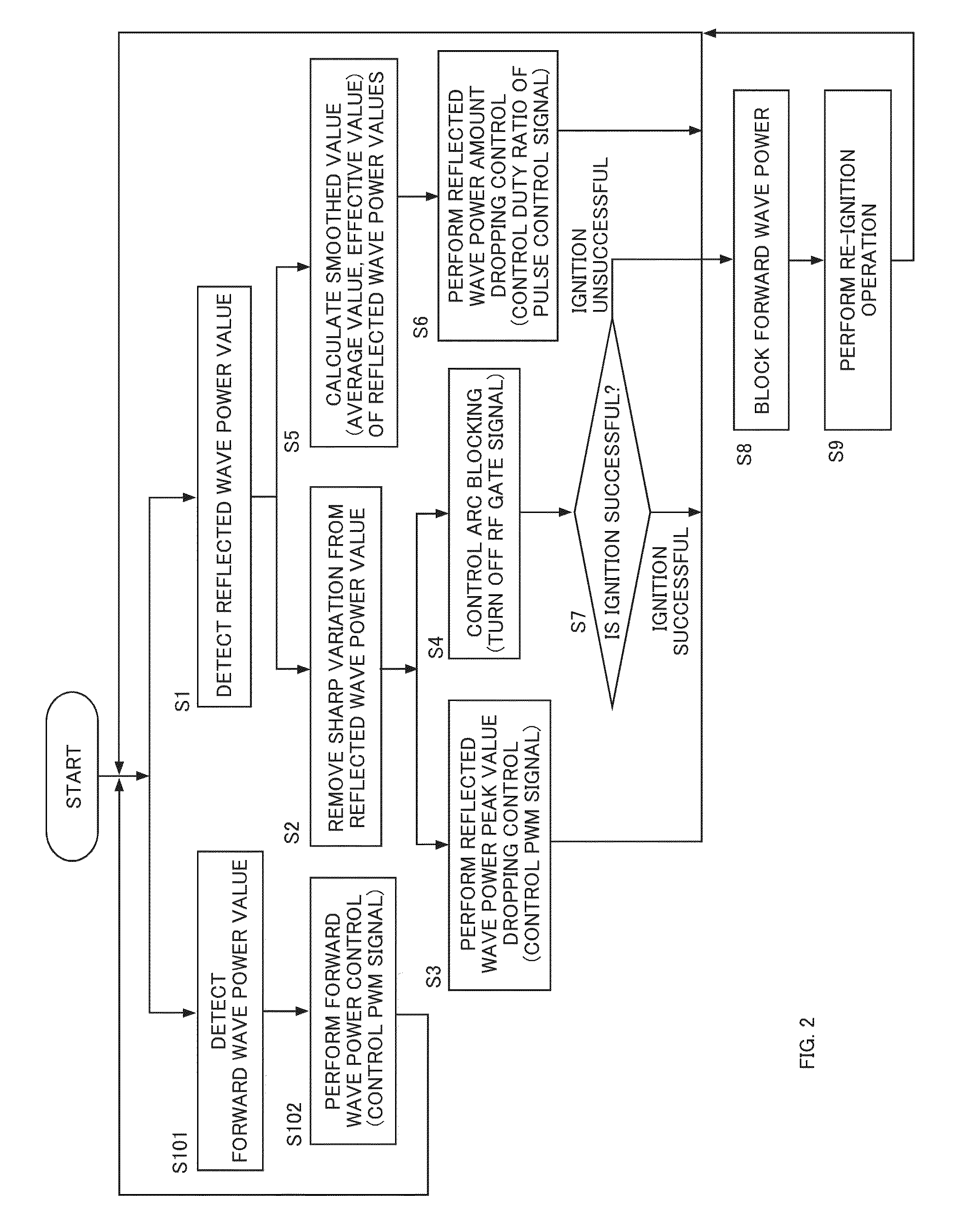
[0119]Embodiments of the present invention are described below in detail with reference to the drawings. The following describes an RF power supplying device and a reflected wave power control method of present invention. An example of the configuration of the RF power supplying device is described with reference to FIG. 4, an example of the operation of an RF amplifier unit is described with reference to FIGS. 5 and 6, and a part of the circuit configuration of the RF power supplying device is described with reference to FIGS. 7 and 8. The operation of a forward wave power control loop system of the RF power supplying device is described with reference to FIG. 9, the operation of a reflected wave power peak value dropping loop system of the RF power supplying device is described with reference to FIG. 10 to FIG. 13, the operation of an arc blocking system of the RF power supplying device is described with reference to FIG. 14 to FIG. 16, and the operation of a reflected wave power ...


PUM


Abstract

In an RF power supply for supplying RF power to a plasma load, reflected wave power control is performed in which the reflected wave power of an RF generator is detected and the RF generator is controlled. For a short-time variation in reflected wave power, control is performed based on a peak value variation in the detection value of reflected wave power. For a long-time variation in reflected wave power, control is performed based on a variation in a smoothed value obtained by smoothing detection values of reflected wave power. A reflected wave power control loop system includes a reflected wave power peak value dropping loop system and an arc blocking system that perform control based on a peak variation in reflected wave power and a reflected wave power amount dropping loop system that performs control based on a smoothed power amount of reflected wave power.

Description

TECHNICAL FIELD[0001]The present invention relates to a reflected wave power control method and an RF power supplying device for controlling reflected wave power that is transmitted from a load side to an RF generator side when RF power is supplied from the RF generator to the load.BACKGROUND ART[0002]An RF generator that converts the DC of a DC power supply to RF AC through the switching operation is known. As this RF generator, a class-D RF generator using a class-D amplifier circuit (Class D: IEC International Standard IEC 60268-3 4 classes of operation) is known.[0003]A class-D RF generator causes the RF power amplifier device to perform the switching operation via the RF gate signal, which has a predetermined duty ratio, to convert the DC of a DC power supply to RF AC and supplies the obtained RF AC to a load as RF forward wave power. The class-D RF generator adjusts the output through the pulse operation. The pulse operation is performed in a driving mode in which ON state and...

Claims


Application Information

Patent Timeline
IPC IPC(8): H01J37/32H02M1/08H02M7/539
CPCH01J37/32174H01J37/32146H02M1/08H02M7/539H05H1/46H01J37/32082H01J37/32183H01J37/32944H01J37/3299H05H2242/26
Inventor YUZURIHARA, ITSUOAIKAWA, SATOSHIKUNITAMA, HIROSHI
Owner KYOSAN ELECTRIC MFG CO LTD
Why Eureka
Try Eureka