High frequency device
a high-frequency device and high-frequency technology, applied in the direction of power conversion systems, dynamo-electric converter control, electric discharge tubes, etc., can solve the problems of not being able to make an optimal setting, not being able to match all load impedances zb>, and not being able to achieve the effect of reducing simple control operation, and lowering the reflected wave power
- Summary
- Abstract
- Description
- Claims
- Application Information
AI Technical Summary
Benefits of technology
Problems solved by technology
Method used
Image
Examples
first embodiment
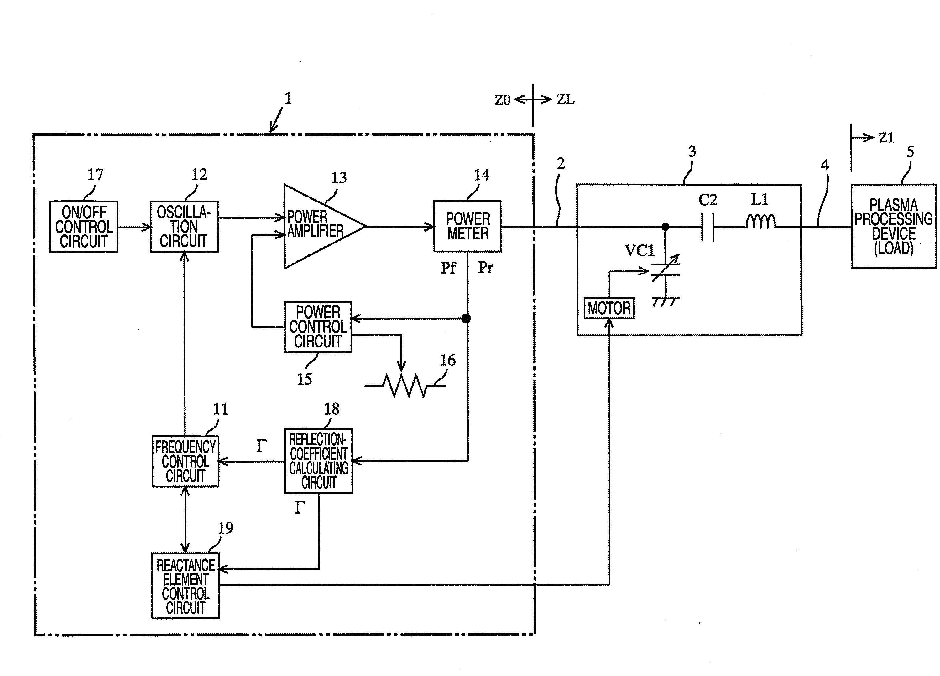
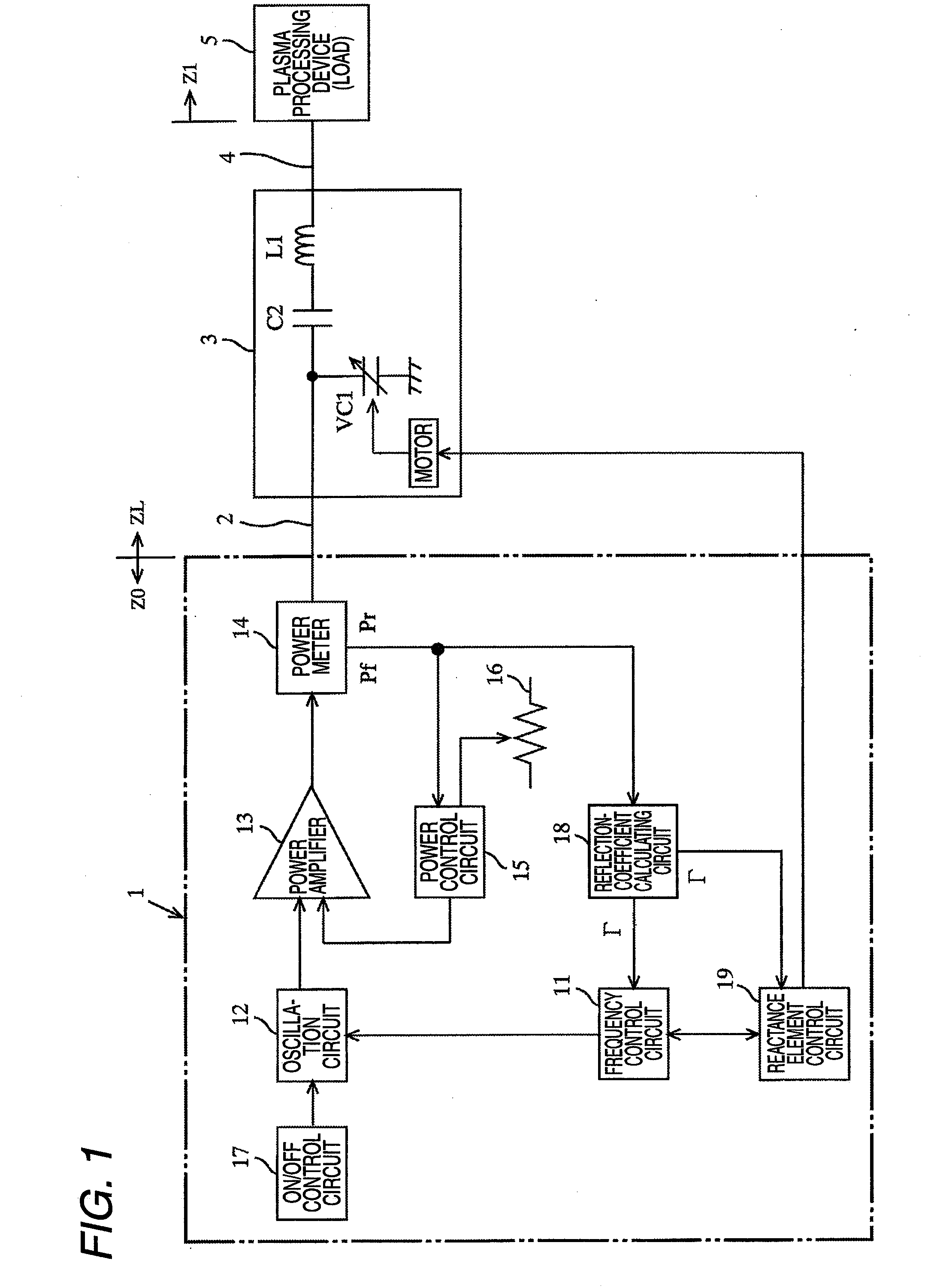
[0060]FIG. 1 is a diagram illustrating an exemplary configuration of a high frequency device according to a first embodiment of the invention and connection relation between the high frequency device and a load 5. The device including a high-frequency power supplier 1 and an impedance adjuster 3 disposed at a downstream of the high-frequency power supplier 1 in a power supplying direction is referred to as the high frequency device.
[0061]The high-frequency power supplier 1 is a system for supplying the load 5 with high frequency power generated by a power amplifier 13 that amplifies a high frequency signal output from an oscillation circuit 12. The high frequency power output from the high-frequency power supplier 1 is supplied to the load 5 through a transmission line 2 formed of a coaxial cable, an impedance adjuster 3, and a load connection portion 4 formed of a shielded copper plate. Generally, such a kind of the high-frequency power supplier 1 outputs high frequency power havin...
second embodiment
[0098]FIG. 4 is a diagram illustrating an exemplary configuration of a high frequency device according to a second embodiment of the invention and connection relation between the high frequency device and the load 5. Additionally, a device configured to combine a high-frequency power supplier 1a and an impedance adjuster 3a is referred to as a high frequency device.
[0099]In the impedance adjuster 3a shown in FIG. 4, the fixed capacitor C2 of the impedance adjuster 3 shown in FIG. 1 is changed into a variable capacitor VC2. The variable capacitor VC2, likewise the variable capacitor VC1, is configured to change capacitance thereof by using a motor. Additionally, the motor, likewise the variable capacitor VC1, is configured to be controlled by the reactance element control circuit 19.
[0100]The high-frequency power supplier 1a is mostly the same as the high-frequency power supplier 1 shown in FIG. 1 but is configured to change the capacitance of the variable capacitor VC2 by controllin...
PUM
 Abstract
Description
Claims
Application Information
 - R&D
- Intellectual Property
- Life Sciences
- Materials
- Tech Scout
- Unparalleled Data Quality
- Higher Quality Content
- 60% Fewer Hallucinations
Browse by: Latest US Patents, China's latest patents, Technical Efficacy Thesaurus, Application Domain, Technology Topic, Popular Technical Reports.
© 2025 PatSnap. All rights reserved.Legal|Privacy policy|Modern Slavery Act Transparency Statement|Sitemap|About US| Contact US: help@patsnap.com


