High-frequency power supply device, and plasma ignition method

a high-frequency power supply and plasma ignition technology, applied in the field of high-frequency power supply devices and plasma ignition methods, can solve the problems of lowering the voltage applied, total reflection state, and fracture of an rf power amplifier provided in the high-frequency power source, and achieve the effect of reliable ignition

Active Publication Date: 2016-06-09
KYOSAN ELECTRIC MFG CO LTD
View PDF0 Cites 5 Cited by
  • Summary
  • Abstract
  • Description
  • Claims
  • Application Information

AI Technical Summary

Benefits of technology

[0053]As described above, according to the plasma ignition method of the high-frequency power supply device and the high-frequency power supply device of the present invention, the high-frequency power source is protected against the reflected wave power, with achieving reliable ignition.

Problems solved by technology

By way of example, natural oscillation of a matching box, an action of plasma ignition, or the like, may be a factor of the reflected wave occurrence, and during a period from the point when the high-frequency output is switched from the off-state to the on-state, to the point when the plasma is ignited, reflection coefficient Γ becomes approximately one (Γ≈1), and this may cause a mismatching state, leading to a total reflection state for a while.
When the reflected wave returns to the high-frequency power source from the plasma load, a standing wave is generated, which is determined by a length of an output cable, and this may cause high voltage and large current of the reflected wave, resulting in fracture of an RF power amplifying element provided in the high-frequency power source.
Reduction of the forward wave power so as to protect the high-frequency power source against the reflected wave power leads to lowering of the voltage applied to the load, and thus, there is a problem that, depending on a recipe condition that restricts atmospheric pressure and gas types, igniting plasma may fail and disable the pulse drive.

Method used


Image

  • High-frequency power supply device, and plasma ignition method
  • High-frequency power supply device, and plasma ignition method
  • High-frequency power supply device, and plasma ignition method

Examples


Embodiment Construction

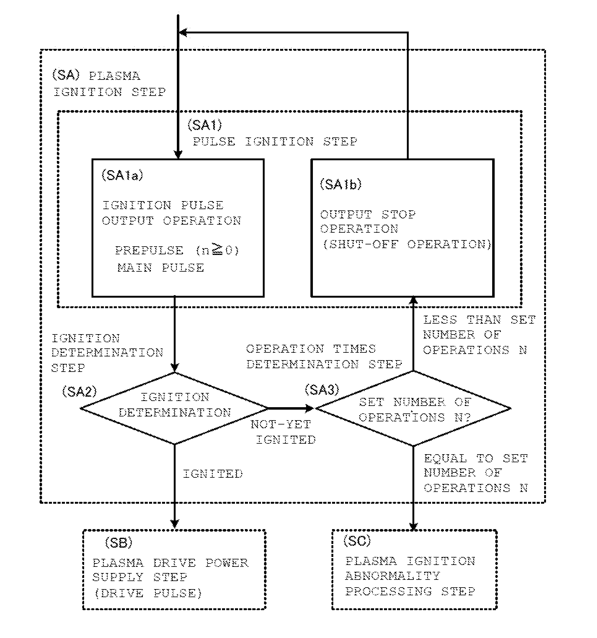
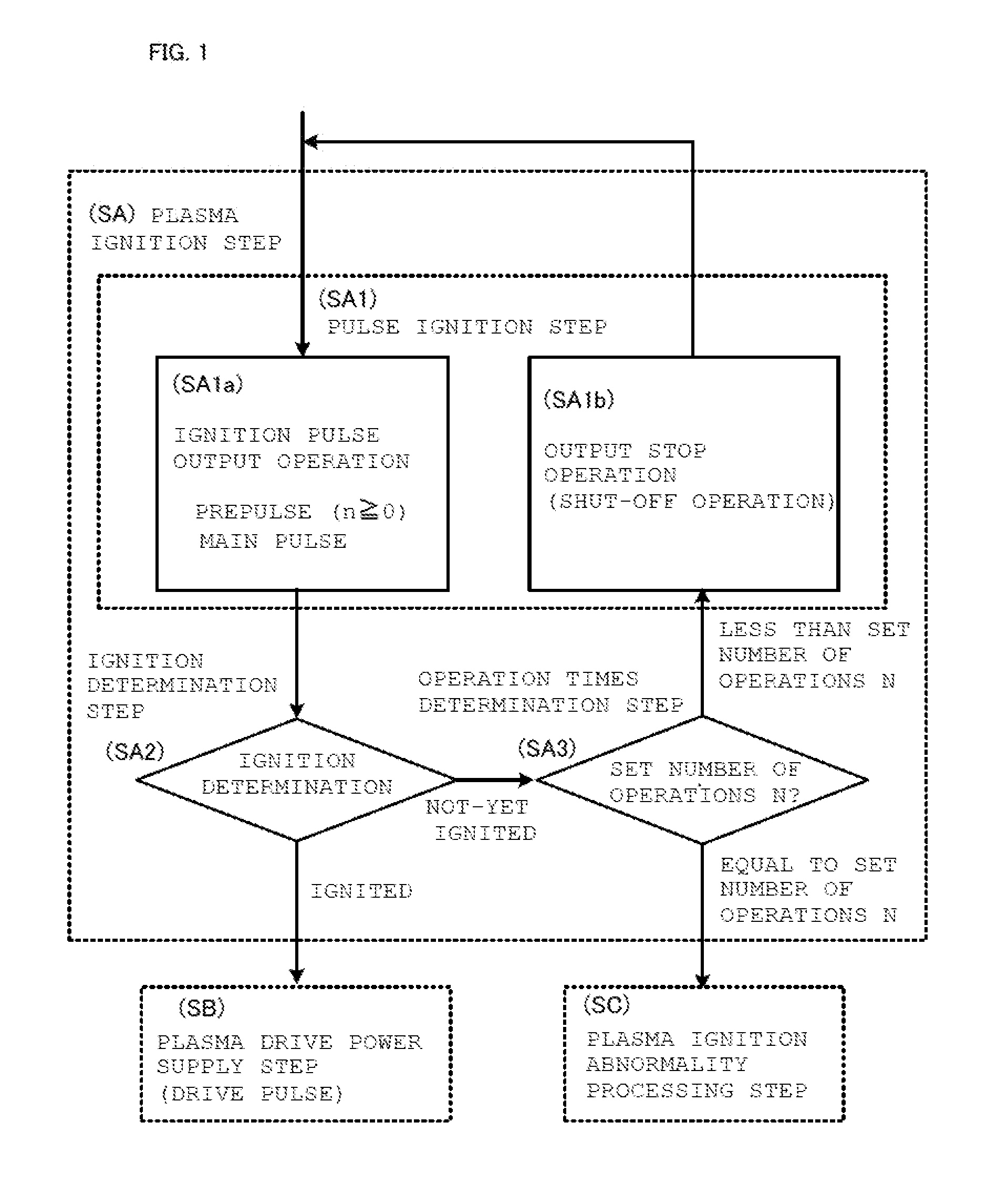
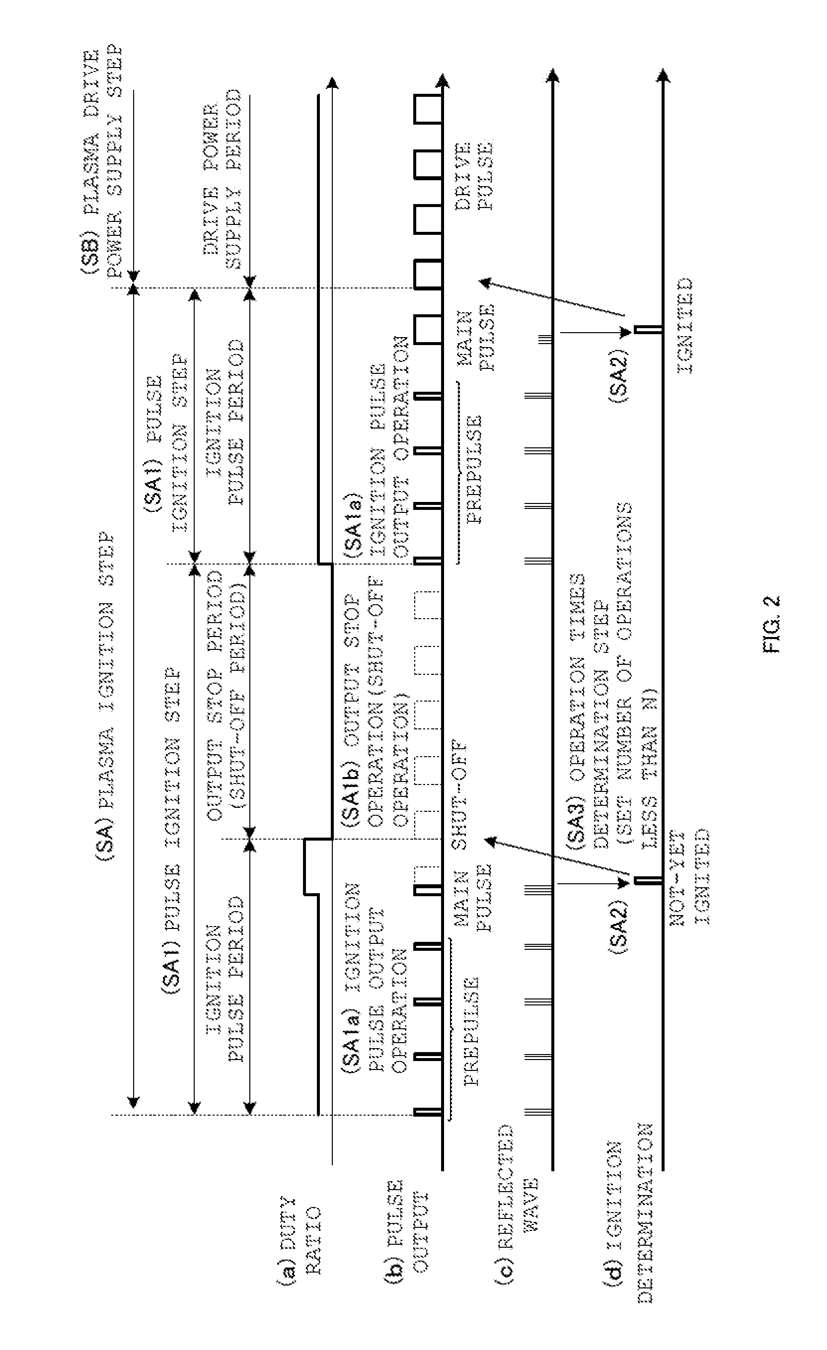
[0078]Embodiments of the present invention will now be described in detail with reference to the accompanying drawings. Plasma ignition according to the high-frequency power supply device of the present invention will be described as the following; schematic operations with reference to FIGS. 1 to 3; an outline configuration with reference to FIG. 4, and an outline configuration of a power controller provided in the high-frequency power supply device with reference to FIG. 5. FIGS. 6 to 18 are flowcharts and signal diagrams for describing two operation examples of the plasma ignition according to the high-frequency power supply device of the present invention. FIGS. 6 to 14 show examples for determining the ignition state at the end of the ignition operation period, and repeating the operations in the ignition operation period for the set number of ignition operations, and FIGS. 15 to 18 show the examples for determining the ignition state during the ignition operation period and re...


PUM


Abstract

A high-frequency power supply device is provided with a plasma ignition step that supplies pulse power to ignite plasma, and drive power supply step to supply drive power for maintaining the plasma being generated. In the plasma ignition step, an ignition pulse being applied in an ignition pulse output operation is configured as including a main pulse that induces ignition, and a prepulse with lower power than the power of the main pulse and being applied at a stage prior to the main pulse. Since the ignition pulse is configured as including the main pulse and the prepulse, this enables protection of a high-frequency power source against reflected wave power, as well as reliably igniting the plasma.

Description

TECHNICAL FIELD[0001]The present invention relates to a high-frequency power supply device for supplying high-frequency power to a load such as plasma, and to a plasma ignition method for supplying high-frequency power to ignite plasma.BACKGROUND ART[0002]It is known that a plasma processing equipment such as semiconductor producing equipment and electronic device producing equipment, and a plasma generator such as a CO2 laser beam machine, utilize plasma that is generated by high-frequency (RF). It is also known that plasma is generated through CW (continuous wave) drive or pulse drive of a high-frequency power source (RF power source).[0003]FIG. 24 schematically illustrates driving of plasma load, using the high-frequency power source (RF (radio frequency) power source). In FIG. 24, pulse output delivered from the high-frequency power source (RF power source) 100 is supplied to load 102, such as a plasma processing equipment and a CO2 laser beam machine, via a matching box 101, th...

Claims


Application Information

Patent Timeline
Patent Type & Authority Applications(United States)
IPC IPC(8): H05H1/46
CPCH05H2001/4645H05H1/46H01J37/32146H01J37/32155H01J37/32174H01J37/32183H01J37/32926H05H1/4645H01T15/00H05B41/24
Inventor YUZURIHARA, ITSUOAIKAWA, SATOSHIOHMA, RYOSUKE
Owner KYOSAN ELECTRIC MFG CO LTD
Why Eureka
Try Eureka