Electric power transmitting and receiving device, electric power transmitting device and electric power receiving device

a technology of electric power transmission and receiving device, which is applied in the direction of near-field systems using receivers, instruments, transportation and packaging, etc., can solve the problems of short transmission and reception range, deterioration of transmission and reception efficiency, and small electric power of transmission and reception, so as to improve user-friendliness, improve transmission and reception efficiency, and improve security

Active Publication Date: 2010-06-17
MAXELL HLDG LTD
View PDF7 Cites 64 Cited by
  • Summary
  • Abstract
  • Description
  • Claims
  • Application Information

AI Technical Summary

Benefits of technology

[0013]According to the present invention, it is advantageous to provide an electric power transmitting and receiving device, an electric power transmitting device and an electric power receiving device, all of which are excellent in transmission and reception efficiency and are improved in

Problems solved by technology

In the electromagnetic induction method, the transmission and reception range is short, and electric power of transmission and reception is small.
However, the transmission and re

Method used


Image

  • Electric power transmitting and receiving device, electric power transmitting device and electric power receiving device
  • Electric power transmitting and receiving device, electric power transmitting device and electric power receiving device
  • Electric power transmitting and receiving device, electric power transmitting device and electric power receiving device

Examples


first embodiment

[0027]First of all, an electric power transmitting and receiving method in the embodiment will be described using FIG. 1.

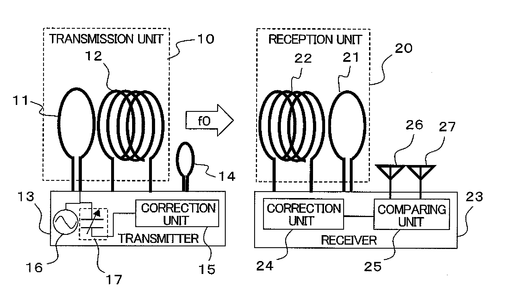
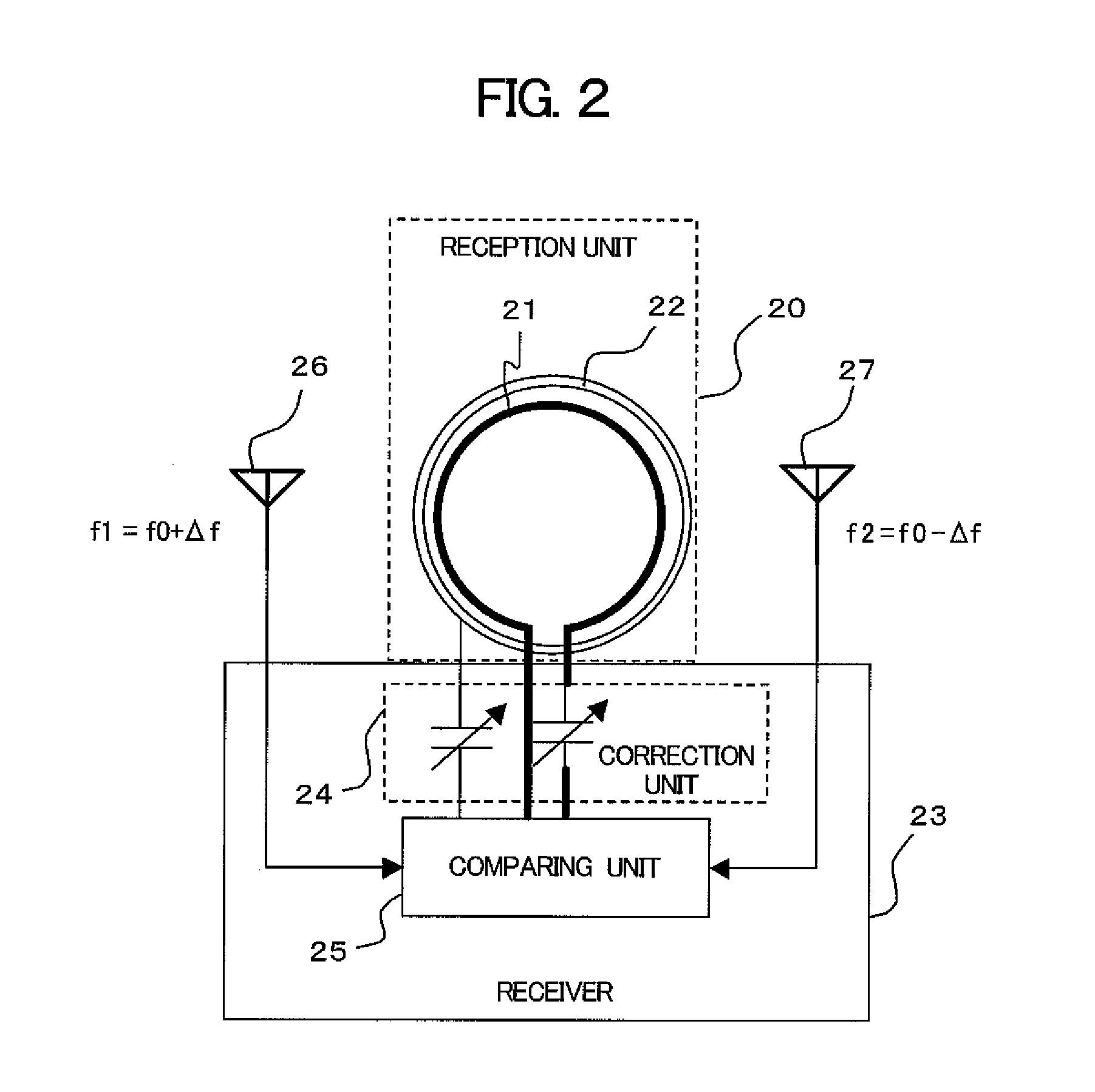
[0028]FIG. 1 is a block diagram of an electric power transmitting and receiving device showing an embodiment of the present invention. In FIG. 1, the reference numeral 10 denotes a transmission unit including a transmission loop 11 and a transmission coil 12. The reference numeral 13 denotes a transmitter which includes a correction unit 15, an oscillation unit (that is also a supplying unit of electric power) 16, and an oscillation frequency adjusting unit 17 and which is coupled to the transmission unit 10 and a correction loop (that is also, as will be described later, a detection unit of electric power or frequencies) 14. The reference numeral 20 denotes a reception unit which includes a reception loop 21 and a reception coil 22. The reference numeral 23 denotes a receiver which is coupled to the reception unit 20 and which includes a correction unit 24, a com...

second embodiment

[0044]The electric power transmitting and receiving device in the first embodiment corrects the resonance frequencies of the reception loop and the reception coil on the basis of the reception levels of the antennas, but the second embodiment is not limited to this. For example, together with the correction amount of the resonance frequency, the resonance frequency of each antenna is simultaneously corrected, so that the correction range of the resonance frequency is widened and it is possible to realize electric power transmission and reception with higher efficiency.. As a modified example of the first embodiment, there will be described an example in which the loop antennas, the reception loop, the reception coil are concentrically arranged on the same plane.

[0045]FIG. 7 is a block diagram of an electric power transmitting and receiving device showing another embodiment of the present invention. Constituent elements similar to those in FIG. 1 are given the same reference numerals...

third embodiment

[0050]The electric power transmitting and receiving device of the first embodiment or the second embodiment corrects the resonance frequencies of the reception unit and each antenna to improve the efficiency by using two antennas whose resonance frequencies are higher and lower than that of the reception unit. However, the third embodiment is not limited to this, but different resonance frequencies are used to realize data communications.

[0051]FIG. 9 is a block diagram of an electric power transmitting and receiving device showing still another embodiment of the present invention. FIG. 9 shows a configuration similar to that of the first embodiment shown in FIG. 1. However, a frequency modulation unit 71 and a processing unit 81 are provided in a transmitter 73 and a receiver 83, respectively. It should be noted that, although not shown in the drawing, the oscillation frequency adjusting unit 17 is provided in the transmitter 73 as similar to FIG. 1. Further, the processing unit 81 ...


PUM


Abstract

In wireless electric power transmission and reception, the efficiency of transmission and reception is improved and a device to which electric power can be supplied is specified to improve security.
Two antennas with different resonance frequencies are provided, and the resonance frequencies of a reception loop and a reception coil of a receiver are corrected in accordance with a reception status of a carrier transmitted from a transmitter to improve the efficiency of transmission and reception. Further, data transmitted from the transmitter are demodulated on the basis of the reception levels of two antennas with different resonance frequencies, and the data are transmitted to the transmitter using a reflective wave to perform data transmission and reception. By using this, device authentication is performed, and security is improved.

Description

CLAIM OF PRIORITY[0001]The present application claims priority from Japanese patent application serial no. JP 2008-319857, filed on Dec. 16, 2008, the content of which is hereby incorporated by reference into this application.BACKGROUND OF THE INVENTION[0002](1) Field of the Invention[0003]The present invention relates to an electric power transmitting and receiving device, an electric power transmitting device and an electric power receiving device, and particularly to an electric power transmitting and receiving device, an electric power transmitting device and an electric power receiving device, all of which are excellent in transmission and reception efficiency and enable data transmission and reception.[0004](2) Description of the Related Art[0005]As a method of wirelessly transmitting and receiving electric power, there have been known electric power transmitting and receiving methods of an electromagnetic induction method using electromagnetic induction and a magnetic resonan...

Claims


Application Information

Patent Timeline
IPC IPC(8): H04Q5/22H04B5/02G06K17/00G06K19/07
CPCH01Q7/00H02J17/00H02J7/025H02J50/12H02J50/20H02J7/00045H02J50/80
Inventor YAMADA, MASAAKITAKAKI, TAKUNIWA, YUHEI
Owner MAXELL HLDG LTD
Why Eureka
Try Eureka