Electrical connector

A technology of electrical connectors and connectors, which is applied in the direction of connections, circuits, parts of connection devices, etc., can solve the problems of small conduction current, large contact impedance, and easy heating of conduction current, so as to reduce heat generation, Effect of dispersing insertion force and reducing insertion force

Active Publication Date: 2019-01-04
DEYI PRECISION ELECTRONIC IND CO LTD PANYU
View PDF8 Cites 0 Cited by
  • Summary
  • Abstract
  • Description
  • Claims
  • Application Information

AI Technical Summary

Problems solved by technology

[0003] However, the plugging method between the electrical connector of this structure and the butt connector is to rely on the insertion of the butt connector into the plug-in space to electrically connect with the tip of each of the thorns, because the thorns The structure is strong, and no elastic deformation will occur when it abuts against the butt connector, so although there are a plurality of the thorns to transmit current, each of the thorns only forms a conductive path, which is likely to cause large contact resistance and conduction. Small current and easy to generate heat when conducting current

Method used


Image

  • Electrical connector
  • Electrical connector
  • Electrical connector

Examples


Embodiment Construction

[0052] In order to facilitate a better understanding of the purpose, structure, features, and effects of the present invention, the present invention will now be further described in conjunction with the accompanying drawings and specific embodiments.

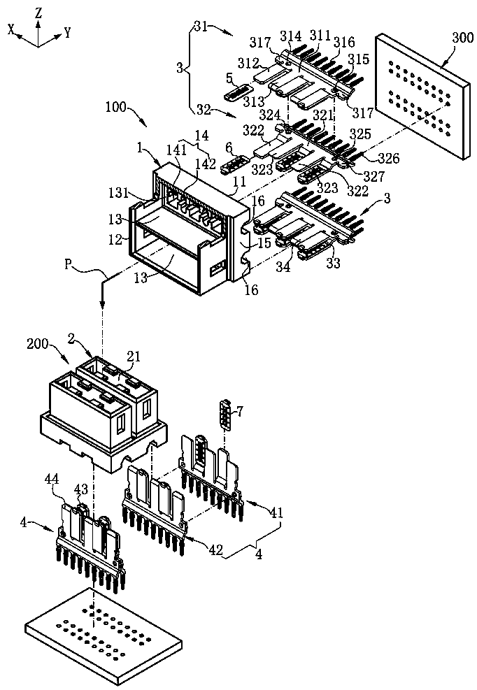
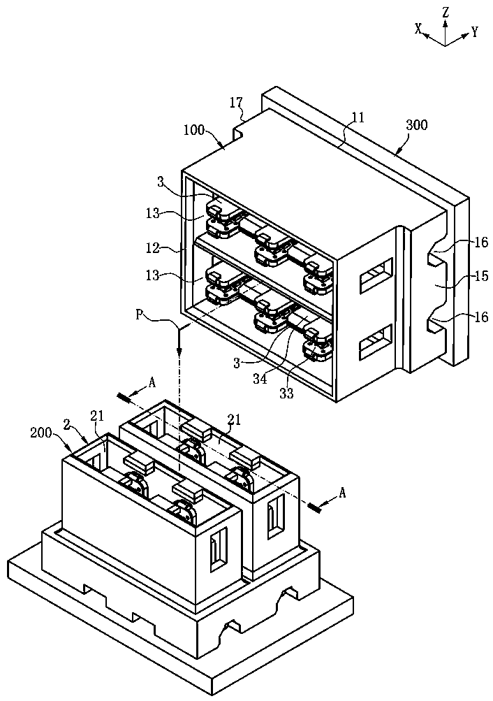
[0053] For the convenience of description, define the Y axis as the front and back direction, the X axis as the left and right direction, and the Z axis as the up and down direction.

[0054] Such as Figure 1 to Figure 2 As shown, it is the electrical connector 100 of the present invention, which is used for inserting with a mating connector 200 along a plugging direction P, which includes a circuit board 300, a first insulating body 1 and is accommodated in the first insulating A plurality of conductive terminal groups 3 of the body 1 .

[0055] Such as figure 1 , figure 2 and Figure 8 As shown, the first insulating body 1 has a mounting surface 11 for mounting on the circuit board 300 and a plugging surface 12 for plug...


PUM


Abstract

The invention discloses an electrical connector, which is characterized in that: an insulating body; A first terminal provided on the first insulating body, the first terminal extending a first extension; A second terminal is arranged on the first insulating body, the second terminal extends a second extension part, and a first accommodation space is formed between the second extension part and the first extension part for plug-in of the mating connector; A first conductive member electrically conductive to the first extension, the first conductive member having a first elastic contact portionpositioned in the first accommodation space, the first elastic contact portion elastically conductive to the mating connector when the mating connector is inserted into the first accommodation space;Second conductive member, electrically conducting the second extension, A second conductive member has a second elastic contact portion located in the first accommodating space, When the mating connector is inserted into the first accommodation space, the second elastic contact part elastically guides the mating connector to reduce the heat generation in the process of large current transmission,optimize the heat dissipation channel to improve the current carrying capacity and connection reliability, and effectively disperse and reduce the centralized insertion force in the past, so as to make the mating easy and soft.

Description

technical field [0001] The invention relates to an electrical connector, especially an electrical connector for transmitting large current and reducing impedance. Background technique [0002] Nowadays, an electrical connector used to transmit large currents is used for plugging with a mating connector. The electrical connector includes an insulating body, and a plurality of or at least two opposite and side-by-side power terminals are accommodated in the insulating body. , each of the power terminals is extended to form a plurality of board ends, the board ends are arranged oppositely and form a plug-in space, each of the board ends is provided with a conductive sheet located in the plug-in space, and each of the board ends The conductive sheet protrudes a plurality of thorns toward the insertion space for conducting with the butt connector. [0003] However, the plugging method between the electrical connector of this structure and the butt connector is to rely on the ins...

Claims


Application Information

Patent Timeline
IPC IPC(8): H01R12/71H01R13/187
CPCH01R12/716H01R13/187
Inventor 金左锋林庆其
Owner DEYI PRECISION ELECTRONIC IND CO LTD PANYU
Why Eureka
Try Eureka