
Connector

A technology of connectors and connectors, which is applied in the direction of connection, conductive connection, bipolar connection, etc., and can solve the problem of easy damage of external conductor contacts

Active Publication Date: 2020-02-11
ROSENBERGER HOCHFREQUENZTECHNIK GMBH & CO KG +2
View PDF5 Cites 0 Cited by
  • Summary
  • Abstract
  • Description
  • Claims
  • Application Information

AI Technical Summary

Problems solved by technology

However, such external conductor contacts can be easily damaged during engagement when the first connector is moved to the second connector by engagement, especially if the first connector is not precisely aligned towards the second connector.

Method used


Image

  • Connector
  • Connector
  • Connector

Examples


Embodiment Construction

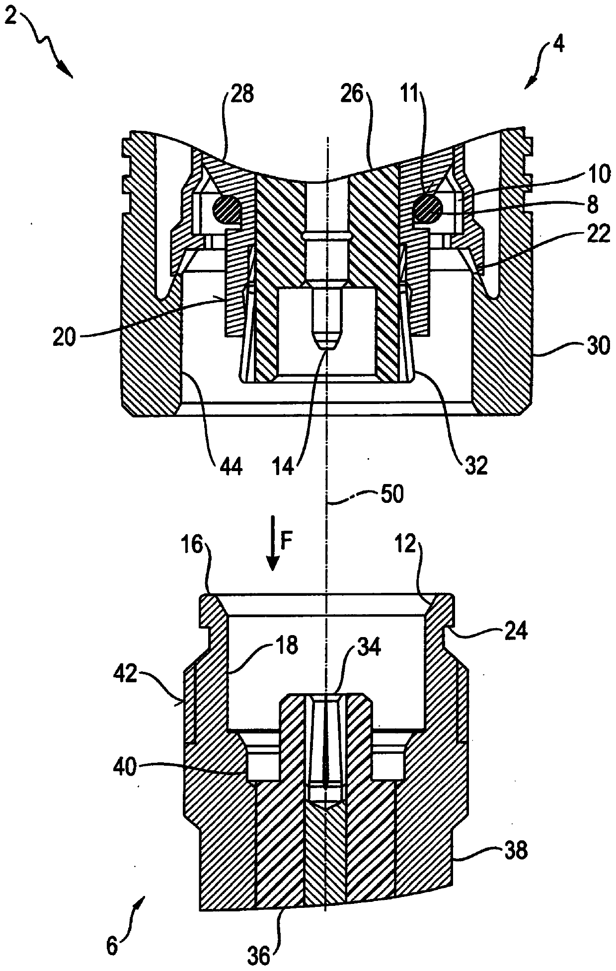
[0029] see first figure 1 .

[0030] The figure shows that the connector 2 comprises a first connection piece 4 and a second connection piece 6 .

[0031] In this exemplary embodiment, the connector 2 is a coaxial connector and a high-frequency connector, wherein the first connecting piece 4 and the second connecting piece 6 can be connected to each other by forming a detent connection. This kind of coaxial connector or coaxial snap lock connector is also called quick lock connector or push-pull connector.

[0032] Coaxial connectors are used for releasable interconnection of coaxial cables. Coaxial connectors are coaxially designed like coaxial cables, whereby they have the advantages of coaxial cables, namely low electromagnetic influence and radiation, good electrical shielding and an impedance equal to the impedance of the connected coaxial cable. impedance in order to avoid reflections at the transition between the coaxial connector and the coaxial cable. Coaxial cabl...


PUM


Abstract

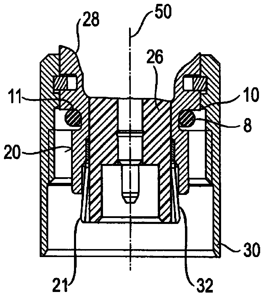
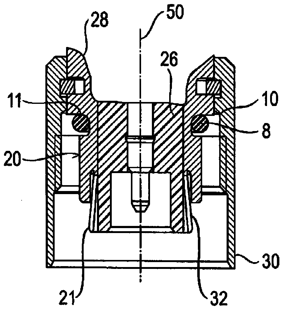
The invention relates to a plug connector (2), especially a high-frequency connector, comprising: a first connecting piece (4), especially a coaxial connector, having a first inner conductor part (14), a first outer conductor part (28) and a first insulating part (26) for retaining said first inner conductor part ( 14); and a second connecting piece (6), in particular a coaxial connector, for axially inserting into said first connecting piece (4) along the joining direction (F), and having a second inner conductor portion ( 34), a second outer conductor part (38) and a second insulating part (36), the second insulating part is used to keep the The second inner conductor part (34); wherein, when the first connector (4) and the second connector (6) are inserted, the first inner conductor part (14) is electrically and Mechanically contacting the second inner conductor portion (34), and the first outer conductor portion (28) electrically and mechanically contacting the second outer conductor portion (38); wherein the first An outer conductor part (28) having a first outer conductor contact section (32) for electrically and mechanically contacting a second outer conductor contact section (40) on said second outer conductor part (38) ; Wherein, the first outer conductor part (28) has a first guide surface (20), and the second outer conductor part (38) has a second guide surface (18), and these guide surfaces are designed such that it is in the When the first connecting piece (4) is inserted into the second connecting piece (6), it can mechanically slide over each other. The first guide surface (20) of the first connection piece (4) and the first outer conductor contact section (32) are axially directed with respect to the longitudinal axis (50) of the connector (2) Arranged at a distance from each other, the second guide surface (18) of the second connection piece and the second outer conductor contact section (14) are axially relative to all of the plug connector (2) The longitudinal axes (50) are arranged at a distance from one another. The first connecting piece (4) has another third guiding surface (44), which is used for passing through the second connecting piece (6) when the first connecting piece (4) is engaged with the second connecting piece (6). The other fourth guiding surface (42) of the two connecting parts (6) cooperates to guide the second connecting part (6).

Description

technical field [0001] The invention relates to a connector, in particular a high-frequency connector, according to the preamble of claim 1 of the patent application. Background technique [0002] A similar connector is known from eg EP2304851B1. The outer conductor contact can be designed as a resilient contact part. However, such external conductor contacts can be easily damaged during engagement when the first connector is moved to the second connector by engagement, especially if the first connector is not precisely aligned towards the second connector. . Contents of the invention [0003] The object of the present invention is to propose a way of improving the interconnection or joining of the first and second connection parts of a connector. [0004] According to the invention, said object is achieved by a connector of the above-mentioned type having the features stated in the characterizing part of claim 1 of the patent application. Advantageous refinements of t...

Claims


Application Information

Patent Timeline
Patent Type & Authority Patents(China)
IPC IPC(8): H01R24/40H01R13/52H01R13/631H01R103/00
CPCH01R13/627H01R13/629H01R13/502H01R13/642H01R2103/00H01R13/5219H01R13/6277H01R13/631H01R24/40H01R24/38H01R9/05
Inventor 马丁·维默尔佛罗莱恩·弗劳恩霍费尔约瑟夫·克劳腾巴赫尔弗朗茨·曼瑟克劳德·布罗谢顿
Owner ROSENBERGER HOCHFREQUENZTECHNIK GMBH & CO KG
Learn More